Continue to Site

Welcome to our site!

Electro Tech is an online community (with over 170,000 members) who enjoy talking about and building electronic circuits, projects and gadgets. To participate you need to register. Registration is free. Click here to register now.

  • Welcome to our site! Electro Tech is an online community (with over 170,000 members) who enjoy talking about and building electronic circuits, projects and gadgets. To participate you need to register. Registration is free. Click here to register now.

need help in replacing mosFETS onan Aluminum pcb of a battery charger.

Status
Not open for further replies.

mvs sarma

Well-Known Member
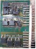
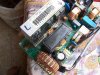
I am attaching two photos of a pcb sub module on aluminum
Please suggest any method , how to remove and replace, as available 120watt iron rendered useless. the part of pcb is split from the heat sink, but has Al base. Thanks in advance.
 

Attachments

  • Aluminum pcb.JPG
    Aluminum pcb.JPG
    65.7 KB · Views: 354
  • charger view.jpg
    charger view.jpg
    248.5 KB · Views: 294
Last edited:
Good grief MVS, how many megabytes are those pictures?

It take ages to load one!

If I understand correctly, the PCB is quite thin but has an aluminium substrate or backing plate.
How is the "body" of the mosfet fixed to the PCB?

Do you need to re-use the mosfets? if not just cut off their legs and try again with your 120w iron to remove the chopped leg from the PCB.

Could you heat up the PCB backing plate by putting it on a hot plate while using the soldering iron on the mosfet pins?

JimB
 
thanks JimB !
i shall try to compress the pictures, but i may loose clarity. let me try. i once tried on stove, perhaps another trial can be made.
PS: now i could compress with some lack of clarity though
the MOSFET is soldered as it is Dpack package. even the dual diodes are also similar
 
Last edited:
You will be lucky to get them off. Its a Thick film unit & not meant to be repaired but replaced. The mosfets will be very hard to remove without damaging the rest of them as the aluminiumn heat sink is removing the heat as designed to do. It would have had the components fixed to the PCB first then the assembly glued to the heatsink. Seen this type of construction in Hitachi tvs back in the early 80s in the vert def.
 
thanks JimB !
i shall try to compress the pictures, but i may loose clarity. let me try.
Yes, much better now!

That unit looks like it needs "fixing with a new one"!
Well fried!

JimB
 
I solder parts in a toaster oven, and some times unsolder parts there.
I hope you can remove the aluminum. If not you will need to get the aluminum to the milting point of solder.
Place the board in the oven. Put some pieces of solder on the aluminum (or PCB)so you can watch for when it reaches temperature.
If the parts are facing up use tweeters to remove the parts you want off. If the parts are facing down drop the board and all the parts will fall off.
You might also have bad resistors.
 
Status
Not open for further replies.

Latest threads

New Articles From Microcontroller Tips

Back
Top