Continue to Site

Welcome to our site!

Electro Tech is an online community (with over 170,000 members) who enjoy talking about and building electronic circuits, projects and gadgets. To participate you need to register. Registration is free. Click here to register now.

  • Welcome to our site! Electro Tech is an online community (with over 170,000 members) who enjoy talking about and building electronic circuits, projects and gadgets. To participate you need to register. Registration is free. Click here to register now.

need help in PLL demodulator project

Status
Not open for further replies.

f1kr1

New Member
I've made a PLl as a demodulator circuit using MM74HC4046. But there is something wrong with it.
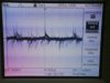
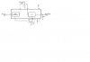
I attach this email with the schematic and the output signal.

R1==100k,R2600k,R33=330k, C1=1.5nF,C2=0.1uF.
the VCO center frequency is 26.7kHz.

The main frequency is 10kHz.
The modulation rate is 1kHz.
 

Attachments

  • output signal pl&#1.JPG
    output signal pl&#1.JPG
    199.2 KB · Views: 186
  • pll demodulator &#9.jpg
    pll demodulator &#9.jpg
    30.4 KB · Views: 161
1) Phase comparator I capture range is only a small percentage of the VCO center frequency. A VCO center of 26.7 kHz and incoming carrier of 10kHz is guaranteed never to capture with PC1.

2) I'm assuming R33 is marked R3 on your diagram. The filter of 330k and 0.1uF is roughly 30 milliseconds. It will completely filter out any modulation above about 30 Hz.

3) I assume R2 is the resistor marked '12' on your diagram and it's 600k not 2600k. The solution on the graphs must be extrapolated to 600k, which suggests to me that C1=1500pF is too large. "As small as possible but larger than 100pF."

4) I'm hoping that you put more effort into checking your construction than you did in proofreading your post.
 
Status
Not open for further replies.

Latest threads

New Articles From Microcontroller Tips

Back
Top