Continue to Site

Welcome to our site!

Electro Tech is an online community (with over 170,000 members) who enjoy talking about and building electronic circuits, projects and gadgets. To participate you need to register. Registration is free. Click here to register now.

  • Welcome to our site! Electro Tech is an online community (with over 170,000 members) who enjoy talking about and building electronic circuits, projects and gadgets. To participate you need to register. Registration is free. Click here to register now.

Need help in controlling Voltage and Current

Status
Not open for further replies.

plmrguest

New Member
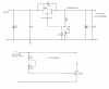
I am trying to control voltage range from 1.5 to 34 using LM338 voltage regulator with 1000u capacitor at the input 430u capacitor at the output with
potentiometer @ the adjustment terminal.

I have 37v and around 5 Amps current at the Vout but when i try to reduce the voltage using potentiometer,resistor 120 ohms burns out. Please suggest
me how to control and get constant Voltage & Current.
 
What did you calculate or R2? **broken link removed**

I would not use a 430 uF cap on the output. Loose it, it's tough for the regulator to do it's job with that there. On PDF page 7, there are suggestions for the value and type of the bypass caps. Bypass caps should be located very close to the IC. The IC may be oscillating because of poor bypassing. Be aware that a minimum load is required, but th 120 resistor should take care of that.

There should be about 1.25 V across R1 or the 120 ohm resistor.
 
I'm guessing that the OP has the pot between Vout and VRef instead of between Vref and Gnd.
 
Here is my schematic for you reference i have both voltage and current , since we can't control both voltage & current
so i need to keep the voltage constant to 32V and current should be adjustable.
 

Attachments

  • power-supply.png
    power-supply.png
    29.2 KB · Views: 309
26V in and 37V (or 32V) out? No way :(.
 
The "current regulation" portion of the schematic does not have a current sensing mechanism; i.e, a resistor or hall cell.
 
Your schematic shows an output voltage that is greater than the input voltage. No linear regulator can do this. If this is not a drafting error, you need to change to a switching boost regulator/converter.

ak
 
Status
Not open for further replies.

Latest threads

Back
Top