Continue to Site

Welcome to our site!

Electro Tech is an online community (with over 170,000 members) who enjoy talking about and building electronic circuits, projects and gadgets. To participate you need to register. Registration is free. Click here to register now.

  • Welcome to our site! Electro Tech is an online community (with over 170,000 members) who enjoy talking about and building electronic circuits, projects and gadgets. To participate you need to register. Registration is free. Click here to register now.

Need Help in Band Pass filter

Status
Not open for further replies.

chenjk09

New Member
Hi
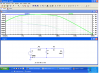
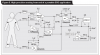
I design a Band pass filter of High pass filter and low pass filter using Multisim 11.0.
While I tested only High pass filter or only low pass filter it can work

While I combine them together it not the value I design why?

Anyone can help me?
Pls download BandPass Filter.pdf for more detail

Thanks
 

Attachments

  • Band-Pass Filter.zip
    353.9 KB · Views: 123
  • BandPass Filter.pdf
    220.5 KB · Views: 295
hi,

Impedance interaction between stages.

You need to make the impedance of the second stage at least 10 times higher than the first stage to get less interaction where you'll see behavior similar to two separate stages.
 
hi,

Impedance interaction between stages.

You need to make the impedance of the second stage at least 10 times higher than the first stage to get less interaction where you'll see behavior similar to two separate stages.

Hi, but I want to design the cut off frequency between 0.05Hz to 100Hz
How should i design on the second stage ? or
Is there any web side to read on it?

Thanks for your reply ;)
 

Attachments

  • bandpass.PNG
    bandpass.PNG
    77 KB · Views: 188
Hi, but I want to design the cut off frequency between 0.05Hz to 100Hz
How should i design on the second stage ? or
Is there any web side to read on it?

Thanks for your reply ;)

Hi,

Im not sure why you want that low frequency so maybe you can explain that.

A simple procedure to design this kind of filter could go like this...

R1 and C1 make up the first stage high pass filter, R2 and C2 make up the second stage low pass filter
Choose your lower frequency f1 and upper frequency f2 and arbitrary R1 to fit the input impedance requirement. Then calculate the following quantities:

w1=2*pi*f1
w2=2*pi*f2
R1=1000
C1=1/(w1*R1)
R2=10*R1
C2=1/(w2*R2)
a=R1*C1*R2*C2
wp=sqrt(1/a)
fp=wp/2/pi
CenterAmpl=(R1*C1)/(R2*C2+R1*C2+R1*C1)

The CenterAmpl above is the amplitude at the center frequency fp. You want to look at this because it will be less than 1.

Design example:

Lower frequency f1=100Hz, upper 500Hz. Choose R1=1000. Do the calculations above:
w1=2*pi*100=628.3185
w2=2*pi*500=3141.59
R1=1000
C1=1/(w1*R1)=1.5915e-6
R2=10*R1=10000
C2=1/(w2*R2)=3.1831e-8
a=R1*C1*R2*C2=5.06606e-7
wp=sqrt(1/a)=1404.9629
fp=wp/2/pi=223.607
CenterAmpl=(R1*C1)/(R2*C2+R1*C2+R1*C1)=0.81967

Note at the center frequency we have a pass gain of about 0.82 which means it cuts a little even at the center frequency. The farther apart the low and high frequencies are the less the cut at the center frequency.
 
Last edited:
Hi,

Im not sure why you want that low frequency so maybe you can explain that.

A simple procedure to design this kind of filter could go like this...

R1 and C1 make up the first stage high pass filter, R2 and C2 make up the second stage low pass filter
Choose your lower frequency f1 and upper frequency f2 and arbitrary R1 to fit the input impedance requirement. Then calculate the following quantities:

w1=2*pi*f1
w2=2*pi*f2
R1=1000
C1=1/(w1*R1)
R2=10*R1
C2=1/(w2*R2)
a=R1*C1*R2*C2
wp=sqrt(1/a)
fp=wp/2/pi
CenterAmpl=wp*C1*R1/sqrt((1-wp^2*C1*C2*R1*R2)^2+(wp*C2*R2+wp*C2*R1+wp*C1*R1)^2)

The CenterAmpl above is the amplitude at the center frequency fp. You want to look at this because it will be less than 1.

Design example:

Lower frequency f1=100Hz, upper 500Hz. Choose R1=1000. Do the calculations above:
w1=2*pi*100=628.3185
w2=2*pi*500=3141.59
R1=1000
C1=1/(w1*R1)=1.5915e-6
R2=10*R1=10000
C2=1/(w2*R2)=3.1831e-8
a=R1*C1*R2*C2=5.06606e-7
wp=sqrt(1/a)=1404.9629
fp=wp/2/pi=223.607
Hampl=wp*C1*R1/sqrt((1-wp^2*C1*C2*R1*R2)^2+(wp*C2*R2+wp*C2*R1+wp*C1*R1)^2)=0.81967

Note at the center frequency we have a pass gain of about 0.82 which means it cuts a little even at the center frequency. The farther apart the low and high frequencies are the less the cut at the center frequency.

Hi,

I doing Analog Front-End for a Electrocardiogram (ECG)

The Band-Pass Filter (BPF) is required to band limit the incoming ECG signal to the desired frequency. The maximum frequency component present in the ECG signal is around 250Hz. But a cut-off frequency of 100Hz is sufficient and often used in the design of ECG for the low-pass filter. As for high-pass filter, its very low cut-off frequency of 0.05Hz may seem to be not necessary. But we shouldn't forget the DC component present in the ECG signal. This last can cause a saturation of amplifiers which are used latter in the design. Therefore it's necessary to add a high-pass filter.

Thanks for your reply :)
 
Hi again,

Ok.

Here is a simpler formula for the center frequency amplitude which is the highest amplitude out of the filter:
CenterAmpl=(R1*C1)/(R2*C2+R1*C2+R1*C1)
 
Your filters are only 1st-order with a slope of only 6dB/octave which is very gradual. They are almost useless as a filter.
You should make a simple 2nd-order or 3rd-order active filter with an opamp that has slopes that are 12dB or 18dB per octave that make a very good filter.
 
I was doing simulation base on the web site shown below

**broken link removed**


Hi again,


Oh ok, if you want to use that very circuit then the center frequency amplitude will be:
CenterAmpl=(C2*R2)/(C2*R2+C2*R1+C1*R1)

where R1 and C1 make up the first stage in your schematic, and R2 and C2 make up the second stage.

Note that the values given ON YOUR LINKED PAGE DO NOT WORK. They wont work at all for your intended purpose.
Better values are as follows:
R1=3.3k
R2=100k
C1=0.33uf
C2=33uf

That gives you a decent pass band and some decent cut on the sides.
 
Last edited:
I was doing simulation base on the web site shown below

**broken link removed**

Besides that the passive "bandpass" filter they show on that site is not very good, they can't even do simple arithmetic correctly. Their calculation for 1/(2*pi*148kΩ*10µF) gets a value of ~107Hz, when in fact the correct result of that calculation is ~.107Hz. No wonder the filter doesn't work very well, besides that the impedance levels of the two stages are too close together.

Furthermore, the notch filter they show a little further down the page is also a very poor design. The response of that notch filter is shown in the attachment; it only attenuates the notch frequency by about 1/2. Also, the notch frequency is not 1/(2*pi*R*C). A simple passive twin-T notch would be better.

If the notch is going to use an opamp, why not simply design a good bandpass filter using the opamp, and include a notch in the transfer function.
 

Attachments

  • ECGnotch.png
    ECGnotch.png
    7.6 KB · Views: 178
Ecg front end

HI All,
Thanks for the reply.
Do you guys know got any simple ECG Front End Circuit to design?

Thanks
 
HI All,
Thanks for the reply.
Do you guys know got any simple ECG Front End Circuit to design?
The datasheet for most instrumentation amplifier ICs has a schematic like this one:
 

Attachments

  • ECG circuit.PNG
    ECG circuit.PNG
    42.3 KB · Views: 206
Last edited:
From the circuit where can the oscilloscope connect?
Where is the output of the ECG Front End?
The output of A3 feeds an RC lowpass filter and can be viewed on a 'scope. It feeds the analog to digital converter IC (ADS8321).
 
The output of A3 feeds an RC lowpass filter and can be viewed on a 'scope. It feeds the analog to digital converter IC (ADS8321).

what is the analog to digital converter IC (ADS8321) for in the circuit?
Is it for transmit out to wireless device like zigbee?
 
what is the analog to digital converter IC (ADS8321) for in the circuit?
Is it for transmit out to wireless device like zigbee?
It can feed a sharp digital filter and be recorded on a pc. It can be viewed on a computer monitor. It can be sent over the internet to a distant doctor.
 
Status
Not open for further replies.

Latest threads

New Articles From Microcontroller Tips

Back
Top