Continue to Site

Welcome to our site!

Electro Tech is an online community (with over 170,000 members) who enjoy talking about and building electronic circuits, projects and gadgets. To participate you need to register. Registration is free. Click here to register now.

  • Welcome to our site! Electro Tech is an online community (with over 170,000 members) who enjoy talking about and building electronic circuits, projects and gadgets. To participate you need to register. Registration is free. Click here to register now.

Need help Identifying a POT

Status
Not open for further replies.

stuhagen

Member
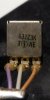
So this is out of an automotive heater controller. This controls the temperature. The PN on the back suggests it is a 3K value. It is a 21 detent 270 degree.
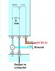
But when you meter it, it reads 25K at the outer terminals. Reading from Wiper to either end, it goes from 22K-25K or 25K-22k....So it is showing an overall
ohm sweep from hi-lo of 3K, but I do not get the reason or why it reads 25k end tap to end tap. Is this a special type of pot? Never seen one like this before.

Picture of the back of this pot, full view, and how it looks in circuit form. (Capacitor is not part of the pot)

Any help directing to this peculiar type of pot would be appreciated.
 

Attachments

  • AC Circuit-2.jpg
    AC Circuit-2.jpg
    21.9 KB · Views: 139
  • Temp Pot (1).JPG
    Temp Pot (1).JPG
    150.5 KB · Views: 137
  • Temp Pot (2).JPG
    Temp Pot (2).JPG
    58.9 KB · Views: 130
Simple, the part number has nothing to do with the actual resistance. Believe your Ohmmeter; I do.

There is nothing special about the actual pot inside, except that it is most likely a "linear taper" pot instead of an "audio taper" pot.


Since it appears to be a "network", you can determine what is inside the box by measuring it ala Thevenin:

Hook a known, steady voltage, like 1.54V from a D-cell across the two outside terminals. Repeat the two following tests at three pot wiper positions: Fully CCW, center, and fully CW:

1. Measure Open Circuit Voltage at wiper relative to the neg side of the battery.
2. Use your meter as a milli-Amp meter, and measure the current from wiper to neg side of battery.

Post the six measurements.

Since it Ohms ok, why do you think you need to replace it?
 
Last edited:
That part number is so convoluted it probably has no bearing on what the resistance actually is. If it were actually a resistance code it would probably be 3 numerical digits rather than literally reading out "3K" because it must accommodate other resistances that the pot may come in.
 
Also, automotive parts are weird. Volumes are not as high as for consumer electronics, but still very high - and labor time is *everything*. I wouldn't be surprised if internally it is a fixed resistor in series with a variable element. Compared to getting the fixed resistor into a wire harness in series with a standard pot, the cost increase for the custom combination part would be almost trivial.

ak
 
Simple, the part number has nothing to do with the actual resistance. Believe your Ohmmeter; I do.

There is nothing special about the actual pot inside, except that it is most likely a "linear taper" pot instead of an "audio taper" pot.


Since it appears to be a "network", you can determine what is inside the box by measuring it ala Thevenin:

Hook a known, steady voltage, like 1.54V from a D-cell across the two outside terminals. Repeat the two following tests at three pot wiper positions: Fully CCW, center, and fully CW:

1. Measure Open Circuit Voltage at wiper relative to the neg side of the battery.
2. Use your meter as a milli-Amp meter, and measure the current from wiper to neg side of battery.

Post the six measurements.

Since it Ohms ok, why do you think you need to replace it?


So I have done this at one point, similar. Fully CCW outputs 5.0v and is max Cool. Full CW voltage drops to near '0 v' at max cool. The voltage and pot sweeps linear. So at straight up middle voltage would be like 2.5v

What gets me in my 40 years of electronics I have never seen a pot display these characteristics. I do not get why measuring from wiper to one end I do not get to '0' ohms. My only thought was there is a built in resistor preventing this.

To answer another question, I have one that is good and one that is bad. So I am trying to repair/replace this for a friend. Bad one is just plain wacky dead.
 

Attachments

  • AC Circuit-2.jpg
    AC Circuit-2.jpg
    33.9 KB · Views: 111
With the good item NOT connected to the car measure the resistance between the pin that is ground and the pin that connects to the 5 volt. This is the value of pot that you require. As it is used as a potential divider the value will not be critical.

Edit. I have just read post #1 again and from your resistance tests it cannot be as shown on the schematic. Try connecting it up to a 5 volt supply and measure the voltage between ground and the slider at both ends of the travel and at the mid point.

Les.
 
Last edited:
Any chance that the "wiper" is not the middle terminal?
 
With the good item NOT connected to the car measure the resistance between the pin that is ground and the pin that connects to the 5 volt. This is the value of pot that you require. As it is used as a potential divider the value will not be critical.

Edit. I have just read post #1 again and from your resistance tests it cannot be as shown on the schematic. Try connecting it up to a 5 volt supply and measure the voltage between ground and the slider at both ends of the travel and at the mid point.

Les.

I really cannot do this. The controller unit is just switches and everything exits out via pins to the main AC Condenser box. So every pin of the pot is open ended. I can supply 5v to the 1 pin and make readings, but I already posted this.

Also, the center pin wire of the pot is indeed the wiper. Verified as the TSET on pinout.
 
I do not get why measuring from wiper to one end I do not get to '0' ohms. My only thought was there is a built in resistor preventing this.
since it is automotive, i would guess it's a custom made part, or something "semi-standard". since in the center pic in the top post, i can see the black resistive material going to the terminals, so the range of the pot is 3k and the ends have built-in resistance. it may be that the 3 k range is all that's needed. so, to replace this pot would require two resistors and a 3k pot (i've never seen one, they're usually multiples of 1, 2 or 5).
 
Last edited:
But according to the voltage measurements, the wiper output voltage goes from 0% to 100% voltage. I suspect that there's an additional fixed resistance in series with the wiper. This wouldn't affect the potential measurements, but would give strange resistance readings.
 
But according to the voltage measurements, the wiper output voltage goes from 0% to 100% voltage. I suspect that there's an additional fixed resistance in series with the wiper. This wouldn't affect the potential measurements, but would give strange resistance readings.
that's another possibility. the closest you will get with a standard pot is probably 2.5k, and put a 22k resistor in series with the wiper. from what you are saying about your measurements though, is that the pot is working.
 
I wanted to report that I bought a 5K pot (didn't have a 3k) and this fixed the issue. Do not know why I got wacky readings but a regular linear 5k pot did the trick. The OEM configuration would go to 5.1v at max but this 5K pot only goes to 4.8v. So I am hoping this is not an issue. 5.0v is max heat and 0.00v is max cool.
 
maybe the wiper connection was oxidized, which would account for the whacky readings.
 
One reason for having a resistance in series with the wiper is for situations where the wiper is connected to a large capacitive load, such as when you need to filter noise from the signal. Without the wiper series resistance, if you turn the knob too quickly, towards one end or the other, you end up with a large voltage across a small resistance and you can fry the pot. So, this could have been a safety measure.
 
Status
Not open for further replies.

Latest threads

New Articles From Microcontroller Tips

Back
Top