Continue to Site

Welcome to our site!

Electro Tech is an online community (with over 170,000 members) who enjoy talking about and building electronic circuits, projects and gadgets. To participate you need to register. Registration is free. Click here to register now.

  • Welcome to our site! Electro Tech is an online community (with over 170,000 members) who enjoy talking about and building electronic circuits, projects and gadgets. To participate you need to register. Registration is free. Click here to register now.

Need help for basketball scoreboard (double digit up/down counter)

Status
Not open for further replies.

patrick_marin

New Member
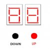
this is a school project.. i am assigned to make a digital scoreboard (basketball) or an up/down counter.

it should be a manual input using a switch. (push a button then the score increases, or push another button the score decreases)

my materials are:
7 segment common anode
74LS47
74LS192
1k ohms resistors
push button switches

i need a schematic diagram to follow.
please help me, im a noob.
thanks.
attached is a proposed design

you can send the diagrams at marin.patrick08@gmail.com
 

Attachments

  • SAMPLE..JPG
    SAMPLE..JPG
    17.9 KB · Views: 3,447
Last edited:
The 74LS47 is a driver for the display. The 74LS192 is an up/down counter which you want to use in its BCD mode, which then will drive the 74LS47 to display the count. Look at the data sheets for these to determine how to use them. After you've looked at these, ask some more questions. We're here to help you with the design, not do it for you. You'll stay a noob forever, if you don't try to do the design yourself.
 
Last edited:
sorry about that

The 74LS47 is a driver for the display. The 74LS192 is an up/down counter which you want to use in its BCD mode, which then will drive the 74LS47 to display the count. Look at the data sheets for these to determine how to use them. After you've looked at these, ask some more questions. We're here to help you with the design, not do it for you. You'll stay a noob forever, if you don't try to do the design yourself.


here is a design i found, will this work?
i understand that between the display and the 74LS192 is the 74LS47.. i already have the idea how to connect them.. my problem is just the switches.. to make it go up when i push a button, or go down.
 

Attachments

  • updowncounter..JPG
    updowncounter..JPG
    54.3 KB · Views: 17,466
Last edited:
Last edited:
Will this circuit work?

I made a revision on the circuit. Will this work? And what kind of switch should be used? Is my connection for the switch proper to make it count up or down? Thank you so much!PROPOSAL..JPG
 
I made a revision on the circuit. Will this work? And what kind of switch should be used? Is my connection for the switch proper to make it count up or down? Thank you so much!View attachment 40874

hi patrick,
You cannot use 9V on the 5V TTL devices, otherwise its looking better.

Have you looked at that link I posted, the coloured drawing is almost what you are looking fro,
 
thank you so much

thank you very much sir eric. i will do diagram you posted.. if there will be any problem, i hope you are still there.. God bless! by the way, what kind of switch is appropriate for the colored diagram? it only uses 1 switch for the counting, am right sir?
 
thank you very much sir eric. i will do diagram you posted.. if there will be any problem, i hope you are still there.. God bless! by the way, what kind of switch is appropriate for the colored diagram? it only uses 1 switch for the counting, am right sir?

hi,
You need at least 2 push button switches, one for UP and one for DOWN count.
I have added a 3rd CLEAR push button, if you need to add a LOAD button later on, use the PL pin.

The 74LS14 will debounce the switch contacts, so that you will not get multiple counts when the buttons are pressed.

DualCntr1..png
 
sir i just have questions, is there a difference between 74LS247 and 74LS47? or they are just the same? and in the diagram, 100n means capacitor? sorry sir i just have a little knowledge about electronics..
 
sir i just have questions, is there a difference between 74LS247 and 74LS47? or they are just the same? and in the diagram, 100n means capacitor? sorry sir i just have a little knowledge about electronics..

hi,
The 100n is a 100nF capacitor also marked as 0.1uF.

The 74LS47 and the 74LS247 have the same pinout.

When you say you pressed the switch and nothing happened, which switch.?

Are you using the circuit I posted yesterday also what voltage battery are you using.?
 
hi,
The 100n is a 100nF capacitor also marked as 0.1uF.

The 74LS47 and the 74LS247 have the same pinout.

When you say you pressed the switch and nothing happened, which switch.?

Are you using the circuit I posted yesterday also what voltage battery are you using.?

thanks for the info sir..
im pressing both switch (one at a time) up or down.. yes i used the circuit you provided..
im using 3pcs AA batteries (1.5v ea total of 4.5v), is that ok sir?
 
thanks for the info sir..
im pressing both switch (one at a time) up or down.. yes i used the circuit you provided..
im using 3pcs AA batteries (1.5v ea total of 4.5v), is that ok sir?

hi,
I guess the switches are normally open single pole switches.??

The +4.5V is a little under specification for 74LS, it should be 4.75V thru 5.25V.

Can you confirm the switches you are using.?

The circuit does work, have you re-checked your wiring.?

Also what are the LED's displaying.?

BTW: My name is Eric.:)

EDIT: do you have voltmeter or any other test equipment.?
 
Last edited:
hi,
I guess the switches are normally open single pole switches.??

The +4.5V is a little under specification for 74LS, it should be 4.75V thru 5.25V.

Can you confirm the switches you are using.?

The circuit does work, have you re-checked your wiring.?

Also what are the LED's displaying.?

BTW: My name is Eric.:)

EDIT: do you have voltmeter or any other test equipment.?

sir eric, i attached the picture of the switch.. it bounce back when you push it, the initial display upon turning on the circuit is 0 4
 

Attachments

  • Picture 2..jpg
    Picture 2..jpg
    18.1 KB · Views: 660
Last edited:
sir eric, i attached the picture of the switch.. it bounce back when you push it, the initial display upon turning on the circuit is 0 4

hi,
OK, see that looks OK.

Do you have a voltmeter.?

Have you fitted the CLEAR switch.???
If you have, when you press it the displays should be '00'
 
sir even the reset switch wont work.. uhm sorry i dont have any tester.. maybe ill just rewire everything again..

hi patrick.
Do you have an ordinary LED and a resistor about 470R..?????
 
yes sir i have 470r and led

OK.
Connect the cathode of the LED [thats the Bar] to 0V on your pcb.
Connect the 470R to the Anode of the LED, at the other end of the 470R connect a short piece of insulated wire, about 10inches should be OK.

Bare about 5mm of the wire end.

Power up the PCB, you can now use the wire end to test different parts of the PCB.

If the voltage is +5V the LED will light bright, if low it will not light.

Test the voltages [using the LED wire] and see what the 74LS14 pins # 4, 8 and 10 show,,, let me know.
 
hi

sir i will just rewire everything to get the 0 0 display, then be back with the switches.. i guess i can give new feedback by tomorrow..

sir i appreciate your help.. ill be back tomorrow.. God bless!
 
Status
Not open for further replies.

Latest threads

Back
Top