Continue to Site

Welcome to our site!

Electro Tech is an online community (with over 170,000 members) who enjoy talking about and building electronic circuits, projects and gadgets. To participate you need to register. Registration is free. Click here to register now.

  • Welcome to our site! Electro Tech is an online community (with over 170,000 members) who enjoy talking about and building electronic circuits, projects and gadgets. To participate you need to register. Registration is free. Click here to register now.

Need Help! About the LED light.

Status
Not open for further replies.

Jasch2011

New Member
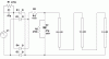
Hi! I need some help from expert. I have bought a LED light, but the brightness seem like too dim, and I want it brighter. Please checked the attached file "diagram.jpg" I was drawn, it is from the circuit board design (I know how to draw, but not the calculation, and sorry for I drawn the + & - DC wrong position).

My questions are,
1. How much power output of is the DC?
2. How to power up the LEDs brightness?
3. Is it because of the 18 nos LED in series cause dim?
4. Or can I redesign it in 6 nos x 3 rows parallel?
 

Attachments

  • Diagram.jpg
    Diagram.jpg
    83.3 KB · Views: 313
Why do you have R2 and C2?
I think thay should be in parallel with the LEDs not series.
 
Last edited:
Why do you have R2 and C2?
I think thay should be in parallel with the LEDs not series.

Thanks for replied. Actually it is a ready product, I was copying their design Into a diagram and need some tech guy to help me figure out what's wrong with it. And so sorry that I am not a tech guy, but i was learnt the basic of electronic during my high school. After nearly 20 years did not touch on electronic stuffs, is like returned the 90% of my knowledge to the lecturer.

Can you explain what is the R2 & C2 functions? And why parallel it?
 
I would short out R2, C2. They are not needed.
Remove R3. It is using up power.

Thanks for replied. Can you explain more, and is it the R2 & C2 put it parallel like 4pyros

I remember what I've learnt previously about the diode place in diamond shape is to convert the AC to DC, but not with R3 in between. Is that any way to get a calculation?
 
With C1 = 220n the LED current is ~ 14mA. It should be safe to increase C1 to 330n (C1 should be an X2 rated cap) to increase the LED current to ~ 21mA (depending on the LED spec), but you would not notice a big increase in brightness. The only way to increase the brightness dramatically is to increase the number of LEDs.
As stated above, remove R2 and C2 (which do nothing useful).
Use R3 as a replacement for R2 (provided it is rated for > 0.5W), to limit any switch-on current surge which might otherwise fry the diodes.
 
Last edited:
Sorry guys, just discovered my huge silly mistake, I drew the wrong diagram. Because I was too sleepy at that moment, saw the wrong connections. Attached with a new one. Please advice again.
 

Attachments

  • New diagram.jpg
    New diagram.jpg
    88.2 KB · Views: 289
I believe this diagram. What is the voltage across R3. This will give us some idea of LED current.
 
The R3 shows from my electronic multimeter is 2.73-2.76V, I am not too sure which is the correct reading. I assume the highest 2.76V is the correct one.
 
Just found an useful info, The C1 has an actual value now. from the Code 400V and 224J = 330pF ±5%, am I correct?
 

Attachments

  • Capacitor value.jpg
    Capacitor value.jpg
    92.5 KB · Views: 497
Last edited:
No, it's not 330pF. It's the second column of 'Value' you should be looking at in the chart. Code 224J means 220000pF (= 220nF), 5%.
I too believe the post #7 circuit, except that C2 is shown with the wrong polarity ;-)
The purpose of C1 is a mains dropper providing an approximately constant current source to the LEDs. It can be increased in value as per post #6.
C2 provides smoothing of the voltage across the LEDs to reduce flicker.
R1 and R2 are for discharging their respective capacitors for safety when the mains is turned off.
R3 limits switch-on surge current as mentioned above.

I can't reconcile a figure of 2.7V across R3 with the other component values shown, particularly the C1 value.

Thanks for sharing with me, I am really feel like back to school again. :) You were explained so clear to me.

For your suggestion, if I want to add on more LEDs, such as 18nos x 3 rows parallel, is that the C2 & R3 need to replace? And what is the actual value?

And what if I want to keep the original design with only 18nos of LED, then like what you've mentioned to changed the C1 only?

I need to make clear on the digital multimeter reading is it correct? From the printed value on multimeter that I set to is 20, mine shows 200m, 2, 20, 200, 500. I guessed that my written value suppose is 27V instead of 2.7V, which means I didn't multiply by 10, right?
 
I am correcting my another mistake, suppose the resistor color code is in front and the gold or silver at last, I was read it the other way round. Now the new value for R1 = 470K Ohms, R2 = 51K Ohms, and R3 = 22 Ohms.
 
Your multimeter probably won't give you an accurate reading for the voltage across R3, because of the waveform. Forget that reading.
If you want to keep with 18 LEDs but increase the current, then make C1 = 330nF (X2 rated, >250VAC), R3 = 1k2 (1Watt rated) and C2 = 100uF (100VDC). The LED current will then be ~18mA average, peaking at ~27mA (which is close to the probable safe limit to prevent burn-out). The brightness won't be much greater than now.
If you add more LEDs it will be more power-efficient to connect them in series with the existing LEDs rather than in parallel.
Here's a suggested circuit with three strings, each of 18 LEDs, in series. Note that C1 is now 470nF (0.47uF), X2 rated, >250VAC.
R1 is 470k (as you mention above), R2 is also 470k, R3 is 1.2k but must be rated at at least 1 Watt.
C2 can be 47uF, but its voltage rating must be > 200VDC.
Don't expect a huge increase in the apparent brightness (because of the ~ logarithmic response of the human eye).
Be aware that all parts of this circuit are potentially at a lethal voltage and due care must be taken in building and using it. Don't go ahead unless you appreciate and accept the risk.
 

Attachments

  • Light.gif
    Light.gif
    14.1 KB · Views: 326
Last edited:
Since the increase voltage won't help a lot in brightness, then the best solutions to replace the LEDs with a higher luminous, and at the same time maintain the original power to have energy saving, reduce heat, and longer lids an for LED. Thanks for the advice.
 
The code on the capacitor is 224 which is 220,000pF or 220n or 0.22uF.
The "4" says how many zeros follow the number 22 in pico-farads.
A code of 331 is only 330pF or 0.33nf or 0.00033uF.
 
You are losing over 100v due to the drop across the LEDs and thus the current though the 0.47 will be only a few milliamp.
 
Status
Not open for further replies.

Latest threads

New Articles From Microcontroller Tips

Back
Top