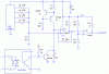
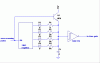
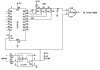
I am trying to take a 4 bit digital signal thru an R2R network and trying to make a varible time delay AC dimmer circuit. What I hope to get is a timed discharge of the cap that will delay a triac gate based on the digital value presented to the R2R resistor network. My problem is that although I understand the digital aspects involved, I have no real clue how to calculate the Resistor or cap values to make an effective dimmer control circuit.. Cab someone take a look at the attached schematic, and help me out. Values do not need to be perfectly linear, I am just trying to control dim incandescent lamps. The circuit is for 120VAC 60 HZ
Thanks
Dialtone
Thanks
Dialtone
")