Continue to Site

Welcome to our site!

Electro Tech is an online community (with over 170,000 members) who enjoy talking about and building electronic circuits, projects and gadgets. To participate you need to register. Registration is free. Click here to register now.

  • Welcome to our site! Electro Tech is an online community (with over 170,000 members) who enjoy talking about and building electronic circuits, projects and gadgets. To participate you need to register. Registration is free. Click here to register now.

Need capacitor and diode help on my circuit

Status
Not open for further replies.

zack501

New Member
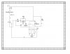
i have attached a copy of the what i have gotten so far. I am wanting to use a 9v battery to power a coil of a TPDT relay (not on the schematic that i attached but will be in parallel with everything else) but also in the circuit i want to have a bi-color 2-lead LED which is green when the switch is closed and when the switch is opened i want the capacitor to power the red for a short period of time. I have gotten it to do this in multisim with the design have however, as i said before, i know little about electronics. For one i wanna know if there is possibly a better way to accomplish this? and i also want to know if it would even work? I know the capacitor in the circuit is probably incorrect i just picked one to try and get it to do what i needed it to so i was wondering which to use. i also have two Schottky diodes in the circuit to stop the relays from just switching on and of instantaneously. i dont know anything about diodes really besides that they only let current travel in one direction but i dont know how they affect the circuit overall. will they work? and which should i use. I noticed in simulation with the addition of diodes the capacitor charged less rapidly but also caused it to discharge slower. I only want the red LED to stay on for like 10 seconds or so. And as far as amperes go. with the setup i have, the amps are very high at first, way to much for a 9v battery, and not that low after a period of time either. I assume the type of capacitor and diodes use affect this greatly and i know i could add some resistors to get the total resistance up and the total amps down (im not exactly sure where they would be placed lol but im sure i could figure it out) and one last thing, I dont want the capacitor to take an hour to charge enough to run the led for 10 secs. Ok i know this is a ton of information and i apologize lol but please help
 

Attachments

  • {F0B8791D-AC5C-4FB1-A348-64767386EF24}.JPG
    {F0B8791D-AC5C-4FB1-A348-64767386EF24}.JPG
    99 KB · Views: 191
You really need a transistor or similar. Relays take a lot of power and so you need a very large capacitor to keep them on. If that is really a 680 mF capacitor, that is a huge and expensive component.
 
I do not want to power the relays with the capacitor. If you look at the schematic i attached you'll see that the only thing being powered by the capacitor when the switch is open is the red LED. i only picked a 680 mF capacitor for the purpose of simulation. I knew it was the incorrect one to use but i wanted the circuit to do what i needed it to first and then work out the details
 
so you want a red led to flash once when relay is closed and green when its open? does the relay open again when red turns off?
 
here let me try and explain the basic concept better. I want to have a circuit with a roller microswitch and a bi-color 2 lead LED. When that microswitch is closed i want one color of the LED (green) to illuminate. when that microswitch is then opened i want the other color of the LED (red) to light up for a short period of time and also blink. And I am hoping to be able to use a 9V battery if possible
 
the red LED only needs to be on for about 10 seconds after the switch is opened and blink about 4 times a second
 
Your circuit doesn't have an oscillator component to make the 4 cps blink rate. Simplest is a 555 timer. And then use the 10 second time constant to override the 555 oscillator to get the initial 10 second long pulse. When the switch is closed, use that to shut down the 555 to avoid blinking the red LED while the green is on. You may have an issue with transistion periods if the switch is closed and open (or vice versa) too close to each other.
 
Status
Not open for further replies.

Latest threads

Back
Top