digitalme1
New Member
hi there, im new to the forum so hi there, ive been building this digital circuit from plans off the internet to electronic control the lead screw of a lathe..all was going well until this circuit plan for pulse division(used to give ratios of spindle speed)..please look at the circuit diagram and read the text of circuit function and tell me if is possible, i dont understand how it can work the way the designer says it does..im a novice to digital electronics so im learning all the time..please point me in the right direction as im stumped, how can you preset this circuit(40193) to zero when counting up or preset it to the preset value when counting down, any help would be greatly appreciated.
designers description
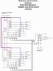
Lead Screw ( = Multiplier) and Main Spindle ( = Divider) Counter (Drawing 6):
Both counters are identical. Since the system is bidirectional, these counters have to be able to reverse their counting direction at any time while counting, without losing a pulse. When counting up, they are initially set to zero and are compared to the preset value. When the preset value is reached, they are set to zero again. When counting down, they are set to the preset value and compared to zero. Upon reaching zero, they are set to the preset value again.
Each time the multiplier or divider counter is set to zero or to the preset value, it passes on a counting pulse to the phase counter. To avoid the phase counter to receive an up count and a down count simultaneously, which would result in an undetermined condition with possible loss of a pulse, pulses from the divider counter (main spindle) to the phase counter are clocked with C4 and from the multiplier counter (lead screw) with C6.
**broken link removed**
designers description
Lead Screw ( = Multiplier) and Main Spindle ( = Divider) Counter (Drawing 6):
Both counters are identical. Since the system is bidirectional, these counters have to be able to reverse their counting direction at any time while counting, without losing a pulse. When counting up, they are initially set to zero and are compared to the preset value. When the preset value is reached, they are set to zero again. When counting down, they are set to the preset value and compared to zero. Upon reaching zero, they are set to the preset value again.
Each time the multiplier or divider counter is set to zero or to the preset value, it passes on a counting pulse to the phase counter. To avoid the phase counter to receive an up count and a down count simultaneously, which would result in an undetermined condition with possible loss of a pulse, pulses from the divider counter (main spindle) to the phase counter are clocked with C4 and from the multiplier counter (lead screw) with C6.
**broken link removed**