Hi I am brand new to this forum and am hoping to learn. I am very new to building circuits and PICs so bare with me. I only have circuits knowledge from physics 2 and circuits for non-EE majors.
I would like to build a circuit board that would allow me to solder 25 buttons from another device onto it and have a PIC control when these buttons are activated.
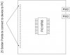
So my question is can you attach 25+ buttons to an 18 pin PIC (like the 16F88) or do you need to have a PIC with pins>25?
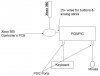
I attached a picture below that I made showing a VERY basic schematic of what I would like. I have 2 PS/2 ports in there because I would ideally like to connect the PIC to a keyboard/mouse to control this device.
Also could anyone give me some advice on how to design a circuit for this? I have Eagle Cad but I have no idea how to build a schematic (where do I need a resistor, capacitor, other types of processors, etc...)
I need help if I am ever going to be able to build something. Thank you.
I would like to build a circuit board that would allow me to solder 25 buttons from another device onto it and have a PIC control when these buttons are activated.
So my question is can you attach 25+ buttons to an 18 pin PIC (like the 16F88) or do you need to have a PIC with pins>25?
I attached a picture below that I made showing a VERY basic schematic of what I would like. I have 2 PS/2 ports in there because I would ideally like to connect the PIC to a keyboard/mouse to control this device.
Also could anyone give me some advice on how to design a circuit for this? I have Eagle Cad but I have no idea how to build a schematic (where do I need a resistor, capacitor, other types of processors, etc...)
I need help if I am ever going to be able to build something. Thank you.
")