Electro Tech is an online community (with over 170,000 members) who enjoy talking about and building electronic circuits, projects and gadgets. To participate you need to register. Registration is free. Click here to register now.
Welcome to our site! Electro Tech is an online community (with over 170,000 members) who enjoy talking about and building electronic circuits, projects and gadgets. To participate you need to register. Registration is free. Click here to register now.
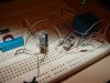
One last issue, I built it and it works, but when the motor is attached. When the relay gets close to the time to release it "chatters" and never releases.
No, wait - take D1 out of the circuit and try it again. This is going to be ground bounce from the load retriggering the device. Too much load for the power supply, pulls the supply down, bounces up again when disconnected. Removing D1 will make the "off" time as long as the "on" time.
That's the problem, the power supply jumps up a couple of volts. Now the question is what's the simplest way to fix it. Is than an SPST or DPDT relay or what?
That's the problem, the power supply jumps up a couple of volts. Now the question is what's the simplest way to fix it. Is than an SPST or DPDT relay or what?
Wait - no, I didn't say SHORT it, I said "take D1 out of the circuit "!
Try it without D1. Leave D2, that's a protection diode.
Also remember that after trying to run it without D2, shorting out D1, and putting the transistors in backwards, those two poor little three-legged 2N2222 troopers may have gone off to the land of eternal silicon rest and need replacement.
One thing What may be the problem is that the output transistor (Q1?) spends a lot of time in the linear region, before the relay trips OFF. And it is still in the linear region even after that. I watched that on the o-scope. With just the relay, it's no big deal. But, when zone added the motor, as the relay tripped OFF and the motor stopped it probably allowed supply voltage to climb, increasing the voltage for the relay, and causing the relay to trip back ON. This restarted the motor, which caused the supply voltage fall, tripping the relay back OFF, stopping the motor, increasing the supply voltage, tripping ON the relay...and on and on and on. That was the chatter on release, Eventually C1 will charge enough to take the transistors into cutoff.
I think the solution would be a "stiffer" power supply, or a separate supply for the motor, or a switching circuit that is more absolute in transition...think Schmidt trigger.
This site uses cookies to help personalise content, tailor your experience and to keep you logged in if you register.
By continuing to use this site, you are consenting to our use of cookies.