Continue to Site

Welcome to our site!

Electro Tech is an online community (with over 170,000 members) who enjoy talking about and building electronic circuits, projects and gadgets. To participate you need to register. Registration is free. Click here to register now.

  • Welcome to our site! Electro Tech is an online community (with over 170,000 members) who enjoy talking about and building electronic circuits, projects and gadgets. To participate you need to register. Registration is free. Click here to register now.

my water meter needs a better voltage divider

Status
Not open for further replies.

dBeau

New Member
I've been trying to follow Ed Cheung's water meter monitor idea and have made some great progress but ran into trouble when I found that I had a bit more noise than he. His circuit works pretty well as shown on his web site though I did have to play with the value of the hysteresis resistor to get a clean transition. Even with that change if the meter parks itself near a transition point I have enough noise to falsely trigger multiple pulses.

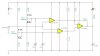
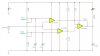
So, I thought I'd get fancy and put two more of the LM339's comparators to work. I figured I'd use one as an S-R flip flop with S triggered by the HI side of the sine wave as detected by one of the comparators and the R triggered by the LO side of the sine wave detected by the other. The idea being that at most I'd get single pulse a bit too early as the noise would be unlikely to reach all the way down to trigger a reset.

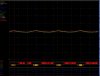
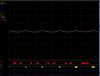
I did a simulation of the circuit using TI-TINA and got some promising results so I decided to build it. The first problem I ran into was the voltage divider. The input signal is a sine wave going between 1.89v an 1.99v and from 0hz to 20hz. The signal range has been constant and the frequency changes (as expected) with water usage. So, I need a voltage divider that will let me set the two outputs to around 1.90v and 1.98v I'd like to be able to adjust both independently or even better pick a center point and a width. On paper what I have looks great. In practice it just doesnt seem to come out right. Tweeking the large value resistors on either end to let the pots do their fine tuning thing is a real exercise in frustration. There's got to be a better way.

Any and all comments on the voltage divider or the circuit in general would be greatly appreciated. ...oh and did I mention I dont know a thing about circuit design?
 

Attachments

  • WATER-METER.JPG
    WATER-METER.JPG
    52.8 KB · Views: 165
hi,
Looking at that circuit, trying to set the threshold of the two comparators when using the same resistive divider chain will be close to impossible.

I have added a second divider on this circuit, using the existing resistor values, as you can see the threshold are well out of the range of your input signal of ~1.9Vac.

I will post a revised circuit later today.;)
 

Attachments

  • Water-meter.jpg
    Water-meter.jpg
    43 KB · Views: 144
hi,
This LTspice circuit shows the resistive dividers for the required thresholds.
Ideally the pots should be 20turn or 2K for precise settings, if you do use a 2Kpot , change the series resistors to suit.

I have not changed the rest of the circuit, but IMO some improvements could be made.
 

Attachments

  • AAesp03.gif
    AAesp03.gif
    51.5 KB · Views: 157
Hi Eric,

Thanks for your replies.

Using two separate voltage dividers sure seems to be the way to go. I replaced what I had with a couple of 500k pots (all I had) and was able to get the voltages I needed with far less trouble (though way to fidgety for my liking). ...time to go shopping.

I wasnt very clear about the nature of the signal and the supply voltage. Vcc is only +5v not 15 (the battery was labeled V1 with a value of 5). Also, the input signal ranges from +1.89v to +1.99v. The first two comparators are trying to catch the tops and bottoms of the sine wave.

Noise from the signal is still a problem. It's starting to look like I have small spikes that span the upper and lower limits. I would have expected this to have been a problem when I was using a single comparator with hysteresis. Should my two limit comparators be configured for hysteresis? On the other hand, wouldnt this noise show up on the scope?

I've attached a screen shot of the noise. The water is running at a bit more than a drip so it's less than .1hz. Ch1 and Ch2 are the inputs to the flip-flop and Ch5 is the output. Perhaps what looks like clear logic levels to me, are widely different voltages to the comparators.
 

Attachments

  • scope1.JPG
    scope1.JPG
    75.1 KB · Views: 127
Hi,

Normally when you use comparators you also use some kind of hysteresis. You should incorporate at least some.
Also, if the noise is very high spikes you may also need some capacitive low pass filtering. That should be simple here because you dont need high frequency response.
Power supply bypassing is also a good idea.
The set point pots would also have caps from center to ground.
 
Last edited:
I wasnt very clear about the nature of the signal and the supply voltage. Vcc is only +5v not 15 (the battery was labeled V1 with a value of 5). Also, the input signal ranges from +1.89v to +1.99v. The first two comparators are trying to catch the tops and bottoms of the sine wave.
hi,
The +5Vs compared to a +15Vs will make a big difference to the circuits operation.

When you say the input signal ranges from +1.89V to +1.99V, does this mean a sinusoidal signal of +/-0.1Vppk sitting on a DC level of +1.94V.??? [query point]

The noise could be coming from your power supply and/or the dividers, the circuit doesn't show any decoupling capacitors.??

As you can see there is hysteresis applied on the output OPA, I would suggest that you consider a low level of hysteresis for the Hi/Lo OPA's.

If you confirm my query I will redo the circuit for +5Vs and that waveform.

BTW: I did sims to confirm that the circuits works OK over 1Hz thru 20Hz
 
Last edited:
1. You should have a bias return path on your sensor input. Can be just about anything. Try 10K to ground.

2. You should always create your references from a reference IC and not the power supply. A 2.5 V reference is common. There can also be problems if the reference applied to your comparitor isn't low Z i.e. buffered
 
hi dB.
Look at this modified circuit for +5Vs and the actual input waveform.
[no changes made to the hysteresis]

Tell me what the type of source of the 20Hz signal, I'll let you know if you need a bias path or not.

Whats the length and type of cable from the sensor to the circuit.??

Also whats the type of PSU thats providing the +5V

Any chance of a link to the original web site so that I can see what the author intended.?
 

Attachments

  • AAesp06.gif
    AAesp06.gif
    48.5 KB · Views: 139
Last edited:
Wow a great set of replies... now I'm going to have to go off and figure out what you guys are talking about!

Eric, your clarification regarding the input single is spot on. I started with Ed Cheung's Water Meter Monitor and am using the newer version of the sensor from Vernier, but they dont have much detail on it. Just as in Ed's circuit, I have connected it through a 4.7k resistor. The cable from the sensor is unshielded and about 15ft long (three conductor, +5v, ground, and signal). The PSU is from an old PowerAce (oddly just like the one in Ed's pictures). The final version will have about a 3ft cable but for now I needed to get the signal to a place where I could work with it.

Regarding decoupling caps, I have a few scattered haphazardly about the board. I didnt put them in the simulation because I wasnt sure where they should go, and the simulation worked fine without them (hey I'm a software guy, what can I say). Advice on where to put them would be helpful.

This picture shows about how I expect the circuit to operate. The spikes on Ch5 (the output) are what I dont expect. On occasion, the noise is high enough to span the setpoints, but that doesnt seem to explain these. Also note that 0hz is a valid signal. It just means that no water is flowing at all so there there should be no changes in the output at this time.
 

Attachments

  • water-scope-typical.JPG
    water-scope-typical.JPG
    87 KB · Views: 132
hi,
Your image of the signals shows that input sine wave is very noisy.
The problem we need to avoid when using hysteresis is that we dont want to change the threshold window too much,,, I will have a ponder!

Will look at your link.

EDIT:
I see that Ed's Hall effect signal trace is also very noisy..

I would suggest that you add a very low pass filter OPA, between the sensor and comparator inputs.

Will run a simulation, let you know.
 

Attachments

  • water_plot.gif
    water_plot.gif
    7.9 KB · Views: 135
Last edited:
Here's another picture showing some noise at 0hz. Again, this is just what I'd expect on Ch1 and Ch2. The signal is near the top and on occasion, the noise puts it over. But, the output, Ch5, is already locked in that direction, so there should be no change. There is a big noise spike in the middle that hits both the upper and lower set points. Here I'd expect (but would love to eliminate) a false output pulse.
 

Attachments

  • water-scope-noise.JPG
    water-scope-noise.JPG
    88.1 KB · Views: 131
hi,
This circuit has a Sallen-Key 2pole, 50Hz cut off freq on the input

Note the reduction in noise [ which has been added to the signal, ie 20mV pink noise]

EDIT:
Added a plot showing the output.
 

Attachments

  • AAesp07.gif
    AAesp07.gif
    47.3 KB · Views: 151
  • AAesp08.gif
    AAesp08.gif
    47.1 KB · Views: 145
Last edited:
Eric,

That sure does clean up the sensor's output quite a bit. Thanks! Sadly, I'm going to have to go shopping before I can test it out.

I am still having trouble understanding how my flip-flop output can see a change while the logic analyzer is not showing an S-R-S pattern on the inputs to the flip-flop. I am sure your filter would help quite a bit, but I still feel there is problem with the logic or the inputs to the flip-flop. Being new to all of this I could be relying on the scope a bit too much to tell me what's going on. From looking at my images, do you see what I mean? Do you think your filter will cure that too?

Is there any chance the fourth comparator could be used to filter the input? I'm trying to keep this as small and as low power as possible. Ultimately it will be powered from the +5v of my 1-wire network with the output pulses counted by a DS2423.
 
I'm getting closer. This picture shows how I'd expected it to work. The nice thing is, it's working as expected. I think it's still going to be important to control the noise a bit better.

It turns out the decoupling caps were the key. Per MrAl's suggestion I added caps from the pot's centers to ground. I also added caps between the limit detector's outputs and ground. All of the flip-flop's output spikes went away. As can been seen in this picture, the transitions are all clean.

I found an online calculator for building low pass R-C filters. On the sensor output I put 4.7k resistor with a 1uf cap. The noise level dropped noticeably. Can I do better without going to the complexity of Eric's filter?
 

Attachments

  • water-meter-pretty.JPG
    water-meter-pretty.JPG
    83.5 KB · Views: 141
Any other progress made on this? I'm working on this same exact project and I wanted to try and build the best circuit I could from the start. Power consumption isn't going to be a problem for me. However, these electronics will be connected to the gauss sensor in the meter pit out by the street. I'll run shielded Cat5e direct burial cable out to box to power things. I'll likely run 12V out to the unit and then just use a 7805 out there. The pulses will come back to the house where the pulse counter will be mounted in an enclosure along with a 1-wire to Ethernet adapter. Once I prototype it I'll likely have a board made.

thanks,

-jr
 
My circuit has been working perfectly non-stop since about the time of my last post in August. My "temporary" set-up includes about 20ft of cat5 between the sensor and the prototype on my workbench. That said, I think you'd do better to keep the distance between the sensor and the circuit as short as possible as I suspect that will help to minimize the noise. A longer 1-wire run is less likely to be affected. The sad part here is that Maxim DS2423 is no longer being made.
 
The longest distance will be on the pulse output of the circuit. The input of the circuit will be connected to the sensor and this will be as short as possible. Likely ~12-15". This will be in the "meter pit" with the water meter by the street. I plan to use a 12V power supply up by the house, sending 12V down the wire to the "pit" where I will use 7805 to power up sensor and op-amps.. The output will then send the digital pulses back to the side of the house where I will count them using a hobby board 1-wire dual counter. The counter will connect via 1-wire to a 1-wire ethernet adapter from embedded data systems and I will read it via the network.

Hopefully hobby boards still has some in stock, otherwise I'll have to go another route? Worst case I could use a uC in there to count the pulses, but would need to battery backup the values (or not and just interpolate any difference if it ever goes back to zero)..

So, the circuit you used was Eric's in post #13 on the board? Any interest in a PC board for it if I get that far?

thanks,

-jr
 
Hello,

Finally received my sensor and took scope outside and played with it. This is powered up with a 12V wall wart + 7805 with no filter caps. So, it is a bit noisy.. Sorry for the bad pics didn't have a better way to capture the output.

Basically the amplitude is about 180mV. The top is 2.17V and the bottom is 1.99V..

So, with the circuit above work? I'm thinking that there will need to be some adjustment of the threshold?

thanks!

-jr
 
Also, in Eric's circuit shown. What is U2 and are both U5 and U6 10k pots? I'm not understanding the specs on this with respect to the "wiper" being .49? What does that mean?

I don't have a concern about power usage since this will have a dedicated power supply and will not be powered via the 1-wire bus. There will be 12V sent out to the device and I'll use a 7805 right there with the sensor and electronics!

Thanks!

-jr
 
Status
Not open for further replies.

Latest threads

Back
Top