throbscottle
Well-Known Member
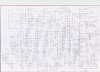
So I have the first full version of the front end for my little bench DMM project now - please see attachment. I'd very much welcome any comments, criticisms, suggestions for improvements and help with selecting parts.
Please ignore the 4 wire ohms bit - I know it's wrong.
I didn't show the coils and drivers for the reed relays. The ones for the ranges, and the AC/DC switch are controlled by the micro-controller, the ones for the functions are controlled by a latching pushbutton circuit (thanks for the help received with that too, folks). I'm using low voltage spco reed relays - I got 12 'cos they were very cheap.
I used a separate input for ohms so I could have a connection straight to the input amp without needing high voltage switching - hence it also has it's own high value scaling resistor. I took advantage of this to put the current input there too. Only 3 of the range switches are needed for the volts ranges - the rest are for the ohms ranges
The input opamp is also used to guard the side of the relay contacts connected to it, and associated wiring - I'd never heard of guarding until a few weeks ago so hope I've done this right.
I cribbed the ohms converter from a datasheet for the LF353 (if anyone can suggest a more up to date device I'd be glad), the SK filter for the RMS converter is cribbed straight from Linear's datasheet, and thanks to ronv for the FET ovp.
The absolute value circuit (OK I missed out a resistor between D1 and U5) is to increment the range on the AC ranges when it's peak input voltage reaches 1v, since the rms converter starts to lose accuracy much above this. The input opamp U3 and output opamp U10 have a combined gain of 6.25 (2.5 each), so the input range bases are 4v, 40v, 400v - there will also be a 400mV range achieved by scaling in the micro. There is a separate high voltage input for whatever KV I can economically build. The HA (High Amps) input will have a shunt with a 75mV output for whatever current it ends up being, since these are plentiful and cheap on eBay... Scaling for this will be done in the micro. Ok I see I forgot to connect it up in the diagram...
The rms function rolls off about 10Hz and somewhere in the 100's of KHz
The 3pF capacitor C5 connected to the input is to take away any high frequency signals which make it through the reed relay's o/c capacitance, which is 3pF. Don't know if this is necessary - there may be enough stray capacitance to do the job anyway. C5 is probably too big - I'm looking for a -3dB point of about <=1MHz - can someone help with this please?
The voltage reference for the adc will be 5v, ±5mV (I think) ISL21009. It has a trim pin, so I'll be looking at how to make best use of that (Intersil recommend using a digital pot, but would it keep it's setting between power up/down?). I would like some kind of auto calibration for the input amp too - I know I can use digital pot's for this.
U8 is supposed to be a 1V reference for the absolute value circuit's comparator - it doesn't need to be terribly accurate.
The analogue 0v will be common with the 0v for the +5v digital supply, but on it's own wire from the psu.
OK that's it - casting myself to the wolves now...
Attachments
Last edited:

