Hello,
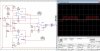
For my lab project i have to setup an infrared range sensing circuit. I will use TK19 105 TSOP1138(i think what is used for tv remote control system) for receiver part. And i have to create a squarewave for after 6 to 70 cycles a gap time of 10 cycles is needed. I setup the circuit attached.. Two different frequencies opamp square wave generator one is 38khz ad other is lower khz.. Then i sum up these voltages then after i put a diot at the output in order to erase negative parts. This way i created the wavelength that is required. However even if i made lots of changes in the circuit i could not properly dedect the square wave with tsop 1138. These devices are broking very easily. Can you advice me how can i idealize my squarewave form and by doing what can i detect this squarewave? I have to use one power supply and elementary materials such as opamps diodes resistors capacitors etc...
For my lab project i have to setup an infrared range sensing circuit. I will use TK19 105 TSOP1138(i think what is used for tv remote control system) for receiver part. And i have to create a squarewave for after 6 to 70 cycles a gap time of 10 cycles is needed. I setup the circuit attached.. Two different frequencies opamp square wave generator one is 38khz ad other is lower khz.. Then i sum up these voltages then after i put a diot at the output in order to erase negative parts. This way i created the wavelength that is required. However even if i made lots of changes in the circuit i could not properly dedect the square wave with tsop 1138. These devices are broking very easily. Can you advice me how can i idealize my squarewave form and by doing what can i detect this squarewave? I have to use one power supply and elementary materials such as opamps diodes resistors capacitors etc...