Hello All,
I am currently working on a chrono project to measure muzzle velocity. The rang will be 0-800 fps or so. Primarily for paintball and airsoft use and also just another project to learn and explore new ideas. I have searched the forums a lot and found a few relative topics but the topic seem to die and are more than a few years old.
The setup,
I am using a BS2 module for computation and control of the LCD panel etc. Compiling the code was not a problem and I can post it here if anyone would like to follow the project and build the unit. The primary setup is that of a simple speed trap which has been discussed several times on the forum but never in this application.
The setup requires two sensors at a set distance apart. The first sensor starts a counter and the second sensor stops it. The counter can them be related to velocity, pretty simple.
My first setup I used two push buttons to test the code and LCD. Everything worked well so I switched to using two IR LED's and two 38.5 Khz IR receiver modules. I chose those module because of being less sensitive to ambient light. The problem was that modulating the LED at 38.5 KHZ uses a lot of resources from the processor making the code very buggy. Also, this setup was very unstable, tripping every few milliseconds.
What I would like to do
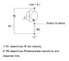
I would like to replace the IR receiver module with a simple IR LED and IR photo transistor. I realize that I would need to use a small signal NPN transistor in conjunction with the photo transistor to get the crisp on/off signal to emulate a push button type setup. I am also aware that I would need to protect the sensor from other light sources. That will not be a problem.
I currently need help on getting a working circuit using this LED, Photo transistor, and NPN transistor. (links below)
Infrared Phototransistor - RadioShack.com
High-Output Infrared LED - RadioShack.com
2N3904 NPN Small Signal Transistor - RadioShack.com
By all means other components will be needed and I am not limited to these components. I also realize pullup/down resistors will be needed.
Any help would greatly be appreciated. Thank you all.
Regards,
I am currently working on a chrono project to measure muzzle velocity. The rang will be 0-800 fps or so. Primarily for paintball and airsoft use and also just another project to learn and explore new ideas. I have searched the forums a lot and found a few relative topics but the topic seem to die and are more than a few years old.
The setup,
I am using a BS2 module for computation and control of the LCD panel etc. Compiling the code was not a problem and I can post it here if anyone would like to follow the project and build the unit. The primary setup is that of a simple speed trap which has been discussed several times on the forum but never in this application.
The setup requires two sensors at a set distance apart. The first sensor starts a counter and the second sensor stops it. The counter can them be related to velocity, pretty simple.
My first setup I used two push buttons to test the code and LCD. Everything worked well so I switched to using two IR LED's and two 38.5 Khz IR receiver modules. I chose those module because of being less sensitive to ambient light. The problem was that modulating the LED at 38.5 KHZ uses a lot of resources from the processor making the code very buggy. Also, this setup was very unstable, tripping every few milliseconds.
What I would like to do
I would like to replace the IR receiver module with a simple IR LED and IR photo transistor. I realize that I would need to use a small signal NPN transistor in conjunction with the photo transistor to get the crisp on/off signal to emulate a push button type setup. I am also aware that I would need to protect the sensor from other light sources. That will not be a problem.
I currently need help on getting a working circuit using this LED, Photo transistor, and NPN transistor. (links below)
Infrared Phototransistor - RadioShack.com
High-Output Infrared LED - RadioShack.com
2N3904 NPN Small Signal Transistor - RadioShack.com
By all means other components will be needed and I am not limited to these components. I also realize pullup/down resistors will be needed.
Any help would greatly be appreciated. Thank you all.
Regards,
Last edited: