Hank Fletcher
New Member
Maybe I'm stating the obvious here, but I'm trying to realize the best way to interface multiple on/off inputs to a PIC.
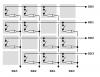
I think I have this right: an 8-bit shift register still uses 4 PIC pins for its operation, providing only twice as many inputs that'd other wise be used. If using multiple shift registers, can you use the same clock and load pins for all shift register ICs, for a greater amount of inputs and also a greater, new-inputs-to-PIC-inputs ratio?
My impression is that it'd be easier to just build a resistor ladder for the inputs, given that most PICs have multiple A/D pins. It shouldn't be hard to get consistent results out of just one A/D pin that way. That's my vote, but maybe I'm missing something?
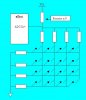
Last edited: