mturner642
New Member
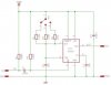
i am trying to control a servo using a 555 timer circuit. i have already designed my timing circuit and have been successful with just signal input to the timer. now i am having problems trying to connect 3 seperate signals into my timer. I am receiving my signals through 3 inductive sensors. The signal goes through my comparator and then checked once again by an AND gate. I have it connected so that each output of the and gate is connected to a single wire running to the timer. I am using 3 different pots to provide 3 different signals to cause the servo to adjust it's angle. When i hook it up in this manner, the servo acts as if there is no signal being sent to the timer.... does anyone know why or perhaps offer any tips?
Thanks,
Marc
Thanks,
Marc