Continue to Site

Welcome to our site!

Electro Tech is an online community (with over 170,000 members) who enjoy talking about and building electronic circuits, projects and gadgets. To participate you need to register. Registration is free. Click here to register now.

  • Welcome to our site! Electro Tech is an online community (with over 170,000 members) who enjoy talking about and building electronic circuits, projects and gadgets. To participate you need to register. Registration is free. Click here to register now.

Multi voltage power supply

Status
Not open for further replies.

bryan1

Well-Known Member
Hiya's,
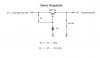
I'm looking for a circuit where I can get +12, -12, +5,-5 and +3.3 volts out. The input will be 24 volts from a 400 amp hour battery bank charged from a solar array. I reckon I could do it using the 78XX and 79XX series of regulators mounted on heatsinks. Tonight after I download the datasheets I'll have a go at doing the schematic but I was wondering if anyone out there had already done this and is willing to share a schematic.

Cheers Bryan1 :D
 
Use the PSU for the Nintendo GameCube system, it has 12V, 5V, and 3.3V output. From the voltages that you want, it almost sounds like you are using this for a video gaming system, and because of the solar array, I would be led to think that you are attempting to make a portable, or perhaps build it into your car. Am I warm?
 
Thanks for the quick reply Nos but ya freezing the point of this power supply is to power a desktop motherboard on 12 volts. I've looked all over the net on this subject but I keep coming up with blanks, however my mates father @ 75 years old said he made one for a 386 and it worked fine. I asked him about using the idea on a 1 gig celeron board and he couldn't see any problem but as it was so long ago he's forgotten how to do it. That's why I'm asking here.

Cheers Bryan1 :D
 
Like I said, use the GameCube PSU. I know that the NTSC model puts out those 3 voltages, and I'm pretty sure that the PAL model does too. If for some reason you can't get your hands on a GCN PSU, you could use an N64 PSU, and regulate part of the 12V line down to 5V.
 
Hi again Nos,
Thanks for the idea for the game cube but I need the negative voltage aswell so that's why I'd prefer to make my own.

Anyway Cheers mate Bryan1 :D
 
You also need much more current for a celeron board than a 78XX regular will handle. I don't know much about the GC supply, but I would suspect it doesn't supply enough current for a motherboard.
 
Simple voltage regulator

Before I go down to the shop and dig around for the circuit I want to describe to you what I did.
I built a low voltage supply using a power transistor, a pot, and a few other small components. I use it with a 12 volt power supply to bring down the voltage to any point I desire.
I don't know squat about this stuff but I think you could just build a reversing switch to reverse circuit polarity.
I am sure the circuit will handle up to 36 volts. I don't know for sure how many amps you can pour through it but I protect it with a 3 amp fuse. I've blown it more than a few times and it still works.
 
Hiya Guys,
The following pic I got from a circuit mag, the description says it can be used in all the 78xx and the 79xx voltage regulators and can pass around 4 amps of current from a 1 amp regulator. If I'm way off base please let me know as I'm in the process of designing it on some veroboard. As far as the 3.3 volts go can anyone suggest a good regulator chip to use. I'd rather use a decidated chip instead of a lm317.

Cheers Bryan1 :D
 

Attachments

  • power_supply1.jpg
    power_supply1.jpg
    26.9 KB · Views: 1,000
1. Those capacitors should not be polarized units (I forgot to remove the plus sign on one of them).
2. You need NPN current-boost transistors for the negative supplies.
3. Vin for each positive supply needs to be at least 4 volts more positive than its respective output. Vin for each negative supply needs to be at least 4 volts more negative than its respective output. You cannot use the same unregulated voltage for all four supplies.
4. Watch out for excessive power dissipation in the regulators and the transistors. You will need heat sinks.
 

Attachments

  • power_supply2.jpg
    power_supply2.jpg
    26.4 KB · Views: 1,109
Hi Ron,
Eh mate thanks for redoing the negative circuit, and on thinking what you said about not being able to use the same supply I should of realized that at the start. But I do have 2 seperate 24 volt battery banks as 1 is a nicad setup and the other is leadacid. So I reckon if I use the seperate banks for the positive and negative rails I might stand a chance of getting this to work. The whole point of doing this by the way all started on me wanting a mp3 player for the shed but the idea of running a desktop will give me the power to interface other stuff aswell. Well tomorrow I'm off to work in the desert for 3 weeks so I'll have plenty of time to work things out but thanks again.

Cheers Bryan :D
 
for the 3.3 volts. used the circuit of lm317.
you can also use a series regulator circuit. a zener diode and transistor.
 

Attachments

  • series_regulator.jpg
    series_regulator.jpg
    12.2 KB · Views: 1,220
Status
Not open for further replies.

Latest threads

Back
Top