Continue to Site

Welcome to our site!

Electro Tech is an online community (with over 170,000 members) who enjoy talking about and building electronic circuits, projects and gadgets. To participate you need to register. Registration is free. Click here to register now.

  • Welcome to our site! Electro Tech is an online community (with over 170,000 members) who enjoy talking about and building electronic circuits, projects and gadgets. To participate you need to register. Registration is free. Click here to register now.

multi position switch (digital dip switch)

Status
Not open for further replies.

baxterdmutt

Member
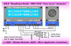
I want to create a digital dip switch with a display. I have looked everywhere for something like this to no avail. Here is what I need it to do. I have a 6 position dip switch and want to be able to cycle through all the available combinations from all off to all on using just 2 push buttons (one to move forward and one to move backwards). I need to display the position as a number on an led display 1,2,3 etc.

I have never done anything like this before. I have worked on radios but this is quite different for me. I am hoping someone here will enjoy taking up the challenge and help me learn.

Thanks in advance for any help.
 
A 6 position dip switch has 64 states. Do you want all 64, or just the six like this: 100000, 010000, 001000, ..., 000001? What do want it to do if it is at the last state 000001, and you try to go up? Likewise, if at 100000 and you try to go down?
 
Firstly, I goofed, I only need this for 5 positions. I do need it for all available positions, I believe that is 32 in total. I would like it to loop through so start at 00000,00001,00011... end at 11111 and then loop back to 00000. The order does not matter. I found a digital rotary switch in this forum that is the right idea but it only turn on 1 of its positions at a time an I need the possibility of any number, or all of the 5 positions on or off. https://www.electro-tech-online.com...ace-rotary-switch-with-digital-circuit.98106/. Maybe there is a way to expand on that concept.
 
I mistakenly said 6 positions when I only need 5. Yes I need all 32 positions. It can start at 00000 and go up in any order (whatever is easiest). When it gets to the end then it should go back to 00000 The led just needs to display 1 to 32.
 
So you need a 5 bit up/down counter, followed by a 5 line to 32 output decoder. They make four bit counters in TTL and CMOS, so you will have to cascade two four bit counters, and add some gating to cause a rollover from state 31 to state zero, and vice versa. They make 4 line to 16out decoders, so two of those (with a modicum of external logic) will do the decoding. Now that you have 32 wires, one of which goes high at a time, what are you going to do with them?
 
I was going to use it on the ctcss module of an old ham radio I have. I am in an area with a number of repeaters that all use different ctcss codes. Flicking a dip switch to change all the time is not pleasant. I appreciate the help but I am not sure I could figure this out. I am a novice when it comes to creating this kind of thing. I was hoping someone might walk me through and I would learn from that. I have a solution with a pic chip but kinda wanted to see how it should be done the CMOS/TTL way.
 
Well, in that case, you dont need to decode the states of the counter, just send the five bits where the dip switch used to be...

I'm out of time today, but maybe someone else can show you how to make a five bit up/down counter.

If you know how to program PICs, why not generate the state counter and even the CTCSS tones inside the PIC? That way you could use a rotary encoder like the frequency knob on your radio to cause the PIC to select which tone.
 
Last edited:
If I were doing this, I would just get a miniature rotary Hex switch (16 states) like this, and add a toggle switch. You will get 16codes with the toggle off, and 16 more with the toggle on. No display is necessary, cause you can read the selected code from the position of the switches.
 
Huh, I had looked around for something like that locally but could only find 8 positions. That is a great idea. I would still like to build the switch I proposed, but not sure I can figure it all out on my own. I think I can figure out how to cascade the 2 counters, but after that I would get lost.
 
Could I just use this circuit and T the counter outputs to where the dip was:

If so I would need to have it stop and loop once it got to 32.
 
Last edited:
Last edited:
Except substitute BINARY counters for the DECADE counters. You still need to add gating to cause the rollover from 31 to 0 when counting up, or 31 to 0 when counting down.
 
Except substitute BINARY counters for the DECADE counters. You still need to add gating to cause the rollover from 31 to 0 when counting up, or 31 to 0 when counting down.

I don't suppose you could point me into the right direction on how to gate that.
 
I don't suppose you could point me into the right direction on how to gate that.
hi,
In the top right circuit of the 4 shown in that Blog, change the 74LS192's to 74LS193's
They are identical pin outs.

Look at the 74LS08 gating which is set for 2mins.
Work out the gate connections that will detect a count of '32' which will generate a RESET to '00'.

Can you follow that OK.?
 
I can follow it in my head but to calculate the gate connection is a mystery to me. I have never done anything that required me to. I am happy to do it myself but I would need some direction as to how.
I am probably wrong but when the second 74LS193 triggers Q1 would that not be 32(which is 33 including 0). If so I could just send it to the reset button, I really wouldn't need any gates, or have I misunderstood the order in which they count.
 
Last edited:
I can follow it in my head but to calculate the gate connection is a mystery to me. I have never done anything that required me to. I am happy to do it myself but I would need some direction as to how.
I am probably wrong but when the second 74LS193 triggers Q1 would that not be 32(which is 33 including 0). If so I could just send it to the reset button, I really wouldn't need any gates, or have I misunderstood the order in which they count.

hi,
Does the existing 6 bit DIP switch pull the 6 lines to 0V or to a high voltage.??
Measure with a DVM the voltage on the DIP switch pins, with a switch closed and open, lets know....
 
.... I have a solution with a pic chip but kinda wanted to see how it should be done the CMOS/TTL way.

Can you pass along a link for that PIC solution, please? I have a PIC solution of my own design so I'm interested to see what someone else has come up with...

Regards, Mike
 

Attachments

  • BB-CTCSS Tone.PNG
    BB-CTCSS Tone.PNG
    35.3 KB · Views: 238
Last edited:
Can you pass along a link for that PIC solution, please? I have a PIC solution of my own design so I'm interested to see what someone else has come up with...

Regards, Mike
Mike,
I don't have the pic solution written yet. If I don't have to I won't do it. I am very slow at writing those things. There is a pic program on the net that you could look at: **broken link removed**
 
Status
Not open for further replies.

Latest threads

New Articles From Microcontroller Tips

Back
Top