Continue to Site

Welcome to our site!

Electro Tech is an online community (with over 170,000 members) who enjoy talking about and building electronic circuits, projects and gadgets. To participate you need to register. Registration is free. Click here to register now.

  • Welcome to our site! Electro Tech is an online community (with over 170,000 members) who enjoy talking about and building electronic circuits, projects and gadgets. To participate you need to register. Registration is free. Click here to register now.

Multi direction DC motor speed control

Status
Not open for further replies.

FireAce

New Member
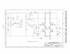
Hey guys, I built the circuit for controlling a dc motor as shown here

https://www.electro-tech-online.com/custompdfs/2010/09/k166.pdf

The only thing I did different, was the 12k resistor. I used a 10k, and two 1k's in series. The unit works fine except for one small problem. When turning the pot from right to left and changing the direction, the unit will handle nicely. When turning from left to right, there is a 4 second delay before the motor will slowly start turning in the opposite direction. Like a capacitor is charging or something. Any idea what the issue here might be?

Thanks
 

Attachments

  • Speed Control.jpg
    Speed Control.jpg
    338.2 KB · Views: 408
Hey Doggy, tried lowering it and shorting it out. Shorting it out messes up everything, lowering it only gives poorer performance. I tried emailing the original creator of the circuit but email doesnt exist anymore. What a bummer. I am building a second one here here in a few days so I want to compare.

Thanks
 
sry, taking a closer look, id say that IC B may be wired wrong and that ICC pin13 should be disconnected from R5 an rewired to the other end (ICB pin5) ...this is just a rookie guess...

**broken link removed**

also i question that whole schematic by the look of the ICC and ICD id wonder if they are just switching on and off without speed control.....try this circuit i designed 4u.... although R4 & R5 values need to be adjusted for sensitivity selection, and R1 & R7 are valued for your on off limits, it should work OK,,

....maybe wait for someone else to OK it for us before you go ahead with it!!!
 

Attachments

  • cap.png
    cap.png
    5.9 KB · Views: 238
Hey doggy, I will try switching Pin 13 to the other side of R5 as you suggested. The circuit at the moment works as speed control and direction, and its pulsing real nicely, as I have run several motors to test. Its the just the delay from left to right, and somewhat a weak response, especially at lower voltage input, like 5v.

Will let you know how it turns out
 
Last edited:
Nope Doggie, that didnt work. I tried taking pin 13 to Pin 5 to avoid the 470k R5 resistor, but it only makes it worse. This is really annoying, just as well I throw it away. No use having to wait 5 min when changing pot from left to right. Wish I could contact the goof that made it.
 
Note: Input is 13v from computer power supply.
Pot fully right I get 11v output.
Fully left I get 13v.

turning Pot to the left the unit responds immediately and performs nicely. Then a bad delay when going back to center and trying to turn pot to the right.


EDIT: I just rebuilt the circuit on solderless breadboard and it works great. Gotta dig now.
 
Last edited:
Status
Not open for further replies.

New Articles From Microcontroller Tips

Back
Top