Continue to Site

Welcome to our site!

Electro Tech is an online community (with over 170,000 members) who enjoy talking about and building electronic circuits, projects and gadgets. To participate you need to register. Registration is free. Click here to register now.

  • Welcome to our site! Electro Tech is an online community (with over 170,000 members) who enjoy talking about and building electronic circuits, projects and gadgets. To participate you need to register. Registration is free. Click here to register now.

Moving message sign in Basic - Anyone done it?

Status
Not open for further replies.

bigal_scorpio

Active Member
Hi to all,

I am trying to make a moving message sign using PicBasic Pro and I am stuck with the part where I send the bytes of the columns to the portB leds and KEEP feeding the data in while moving it along.

All I can find on the net is ASM versions and I don't understand ASM at all. There are many working HEX files that I could simply use but then I still wouldn't know how it works. I am not asking for a full program writing for me but I really need some examples to get me going in the project.

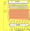
My display is a 5 x 7 LED matrix and has portB running the rows and portC scanning the columns through transistors. I just can't get my head around the idea of loading the the data in AND moving it along.

Any help or examples would be gratefully appreciated.

Thanks for looking........Al
 
Hi Ian,

No mate, Eric USED to live in Rotherham, in fact he was only doors away from where I live, but that was before I knew him.

Also thanks for the conversion offer, I will dig out the best MM sign prog and post it.

Thanks Al
 
Hi Ian,

This seems the simplest useful one I found.

Here is the ASM.

Thanks mate.......Al
Code:
         Experiment-12 for "5x7 Display" Project     
                                 RUNNING SIGN 
             ;Program for PIC16F84 and only F84 chip
             ;Takes data from Table1 and runs it across the screen

 Start ORG 0x00             ;This sets up the ports 
          BSF 03,5
          MOVLW 00h
          MOVWF 05h
          MOVWF 06h
          BCF 03,5
          GOTO Run1

              ;Table1  holds the hex values for each column of LEDs

 Table1 ADDWF 02h,1         ;Add W to Program Counter
             RETLW 00h
             RETLW 40h
             RETLW 40h
             RETLW 7Fh
             RETLW 40h
             RETLW 40h
             RETLW 00h
             RETLW 7Fh
             RETLW 49h
             RETLW 49h
             RETLW 41h
             RETLW 41h
             RETLW 00h
             RETLW 3Fh
             RETLW 40h
             RETLW 3Fh
             RETLW 40h
             RETLW 3Fh
             RETLW 00h
             RETLW 3Eh
             RETLW 41h
             RETLW 41h
             RETLW 41h
             RETLW 3Eh
             RETLW 00h
             RETLW 70h
             RETLW 0Eh
             RETLW 01h
             RETLW 0Eh
             RETLW 70h
             RETLW 00h
             RETLW 7Fh
             RETLW 00h
             RETLW 7Fh
             RETLW 10h
             RETLW 0Ch
             RETLW 02h
             RETLW 7Fh
             RETLW 00h
             RETLW 3Eh
             RETLW 41h
             RETLW 45h
             RETLW 45h
             RETLW 36h
             RETLW 00h
             RETLW 32h
             RETLW 49h
             RETLW 49h
             RETLW 49h
             RETLW 26h
             RETLW 00h
             RETLW 7Fh
             RETLW 00h
             RETLW 3Eh
             RETLW 41h
             RETLW 45h
             RETLW 45h
             RETLW 36h
             RETLW 00h
             RETLW 7Fh
             RETLW 10h
             RETLW 0Ch
             RETLW 02h
             RETLW 7Fh
             RETLW 00h
             RETLW 00h
             RETLW 00h
             RETLW 00h
             RETLW 0FFh

 Run1      CLRF 11h           ;Clear the Ghost locations ready for starting 
               CLRF 12h
               CLRF 13h
               CLRF 14h
               CLRF 15h
               MOVLW 00
               MOVWF 19h      ;File 19h is the jump value for table
 Run2     MOVLW 40h
               MOVWF 18h      ;File 18h counts the number of scans
               CALL Shift         ; and controls the "run speed"
               INCF 19h,1
               MOVF 19h,0      ;Put jump value into W 
               CALL Table1
               MOVWF 15h      ;W contains table data - put it in 15h
               XORLW 0FFh     ;If table value is FF, 
               BTFSC 03,2        ; bit 2 of file 3 will be SET (=1)
               GOTO Run1       ;Start Table1 again
 Run3     DECFSZ 18h,1    ;Scan the display 40h times
              GOTO Run4
              GOTO Run2
 Run4     CALL Scan
              GOTO Run3

 Scan    BSF 05,1               ;Reset 4017
             NOP
             BCF 05,1

            MOVF 11h,0           ;Output the data at the 5 Ghost
            MOVWF 06h           ; locations to the display
            CALL DelD
            MOVF 12h,0
            MOVWF 06h
            CALL DelD
            MOVF 13h,0
            MOVWF 06h
            CALL DelD
            MOVF 14h,0
            MOVWF 06h
            CALL DelD
            MOVF 15h,0
            MOVWF 06h
            CALL DelD
            RETURN

       ;SHIFT moves the data one place to the left to give the "movement"
       ;  effect on the screen

 Shift    MOVF 12h,0         ;Move file 12h to W
            MOVWF 11h         ;Move W to file 11h
            MOVF 13h,0         ;Move file 13h to W
            MOVWF 12h         ;Move W to file 12h
            MOVF 14h,0         ;Move file 14h to W
            MOVWF 13h         ;Move W to file 13h
            MOVF 15h,0         ;Move file 15h to W
            MOVWF 14h         ;Move W to file 14h
            RETURN

 DelD   DECFSZ 1Bh,1      ;Delay for viewing the 
           GOTO DelD            ; column of LEDs
           MOVLW 00h
           MOVWF 06
           Clk BSF 05,0           ;Clock the 4017 to
           NOP                        ; the next output
           BCF 05,0
           RETURN

           END
 
hi Al,
If you now have MPLAB IDE installed, here are the asm and hex files, run OK in simulation.
 

Attachments

  • Als_Scroll1.asm
    4.6 KB · Views: 178
  • Als_Scroll1.hex
    804 bytes · Views: 150
You have used my Running LED program, which is over 10 years old.

See my 15x7 Project: 15x7 DISPLAY for coding that uses "equ" and is much easier to follow.

If you want to understand how the instructions produce the effects, you need to work with assembly coding.

Colin Mitchell
 
Last edited by a moderator:
hi Al,
If you now have MPLAB IDE installed, here are the asm and hex files, run OK in simulation.

Hi Eric,

Thanks mate I will give them a try. Ian is hopefully converting the code so I will then be able to actually see how it all works.

Al
 
Eric I'm converting it to basic for him now.. I also decided to stick ALL the letters A through Z so there's an easy way to change the message!

Cheers Ian

Hi Ian,

Can't wait to actually see how it all works in basic. I always learn more from examples than I ever can by just reading about things.

Thanks mate.....Al
 
You have used my Running LED program, which is over 10 years old.

See my 15x7 Project: 15x7 DISPLAY for coding that uses "equ" and is much easier to follow.

If you want to understand how the instructions produce the effects, you need to work with assembly coding.

Colin Mitchell
TALKING ELECTRONICS.

Hi Colin,

I realised that the project was oldish, but its young to me. ;)

I have looked at the 15 x 7 and it is indeed a real stunner, loads more control and options but I am trying to slowly take in the actual methods of it. Ian above has offered to convert the old 5 x 7 to basic for me and that will really help me, as much as I would like to I can't get my head around ASM.

Maybe in another few decades I will get the hang of it. hehehe

Al
 
This was done in oshonsoft basic, shouldn't be hard to transpose to PBP

Code:
Define CONF_WORD = 0x23c4
Define CONF_WORD_2 = 0x3eff

EEPROM 0x00, 0x3f, 0x44, 0x44, 0x44, 0x3f, 0x7f, 0x49, 0x49, 0x49, 0x36, 0x3e, 0x41, 0x41, 0x41, 0x12, 0x7f, 0x41, 0x41, 0x41, 0x3e  'ABCD
EEPROM 0x14, 0x7f, 0x49, 0x49, 0x49, 0x41, 0x7f, 0x48, 0x48, 0x48, 0x40, 0x3e, 0x41, 0x41, 0x45, 0x16, 0x7f, 0x08, 0x08, 0x08, 0x7f  'EFGH
EEPROM 0x28, 0x00, 0x41, 0x7f, 0x41, 0x00, 0x02, 0x41, 0x7e, 0x40, 0x00, 0x7f, 0x08, 0x14, 0x22, 0x41, 0x7f, 0x01, 0x01, 0x01, 0x01  'IJKL
EEPROM 0x3c, 0x7f, 0x40, 0x20, 0x40, 0x7f, 0x7f, 0x30, 0x08, 0x06, 0x7f, 0x3e, 0x41, 0x41, 0x41, 0x3e, 0x7f, 0x48, 0x48, 0x48, 0x30  'MNOP
EEPROM 0x50, 0x3e, 0x41, 0x45, 0x43, 0x3f, 0x7f, 0x48, 0x44, 0x42, 0x31, 0x32, 0x49, 0x49, 0x49, 0x26, 0x40, 0x40, 0x7f, 0x40, 0x40  'QRST
EEPROM 0x64, 0x7c, 0x02, 0x01, 0x02, 0x7c, 0x60, 0x1e, 0x01, 0x1e, 0x60, 0x7f, 0x02, 0x04, 0x02, 0x7f, 0x63, 0x1c, 0x08, 0x1c, 0x63  'UVWX
EEPROM 0x78, 0x60, 0x18, 0x07, 0x18, 0x60, 0x43, 0x45, 0x08, 0x51, 0x61  'YZ

Dim x As Byte
Dim y As Byte
Dim offset As Byte
Dim message(72) As Byte
AllDigital  'set all pins to digital
TRISA = 0
TRISB = 0  'Portb all outputs
TRISC = 0  'Portb all outputs
ADCON1 = 0

WaitMs 120

Call loadarray()
x = 0
loop:  'main loop 5 x 4ms = 20ms = 50hz
For y = 0 To 10  'Works out 3 shifts a second
	PORTA = 0x1
	PORTB = message(x)  'First line
	WaitMs 4
	offset = x + 1
	PORTA = 0x2
	PORTB = message(offset)  'Second line
	WaitMs 4
	offset = x + 2
	PORTA = 0x4
	PORTB = message(offset)  'Third line
	WaitMs 4
	offset = x + 3
	PORTA = 0x8
	PORTB = message(offset)  'Forth line
	WaitMs 4
	offset = x + 4
	PORTA = 0x10
	PORTB = message(offset)  'last line
	WaitMs 4
Next y
	x = x + 1  'shift one pixel
	If x > 66 Then x = 0  'If we get to 67 then we have done all lines
	Goto loop  'loop forever
End                                               

'Message area
Proc loadarray()
Dim y As Byte
Dim x As Byte
Dim fetch As Byte
Dim char As Byte
Dim col As Byte
Dim row As Byte

char = 0
	For x = 0 To 66 Step 6  'Each character is 5 bytes
		fetch = LookUp("HELLO WORLD "), char
		char = char + 1
		If fetch = 32 Then  'Ive made spaces into 4 blank lines
			For y = 0 To 4
				row = x + y
				message(row) = 255
			Next y
		Else
			fetch = (fetch - 65) * 5  'this is to find the offset in memory of each character
			For y = 0 To 4
				row = x + y
				Read fetch, col
				message(row) = 255 - col  'Invert the bits (You may not need to do this)
				fetch = fetch + 1
			Next y
			row = x + y
			message(row) = 255

		Endif

	Next x
End proc

I placed the letter table in eeprom the load it into a 72 byte array for displaying .. The 4ms delay gives about 50hz and the 0 to 10 gives about three shifts a second

Hope this helps Cheers Ian
 
Last edited:
Each line of the program in the two projects mentioned above, has a comment, plus the discussion in the article explains how and what the program is doing. You cannot possibly expect to understand how a program works until you build, and work on, at least 100 projects. You are expecting far too much, to understand what is happening, if this is your first exercise. You will find the 5x7 is a set of experiments and the previous experiments cover much simpler things, like blinking a LED and producing a tone etc.
 
Al.. When you run this. If there are area's that I need to comment on.. Please let me know but basic has that "readable" characteristic all on its own.

Cheers Ian

P.S. Ive updated the program to include comments

Just made it run with two matrix leds one on portb and the other on portc
 
Last edited:
You have used my Running LED program, which is over 10 years old.

See my 15x7 Project: 15x7 DISPLAY for coding that uses "equ" and is much easier to follow.

If you want to understand how the instructions produce the effects, you need to work with assembly coding.

Colin Mitchell
TALKING ELECTRONICS.

Hi Colin,

I'm trying to construct your 15x7 LED Display but got confused on the following part of the schematic..

RA4 is DIRECTLY connected to BASE BC547? and the 2k2 resistor to +5VDC?

Also all the tact switches terminals that are connected together all connects to BC547 collector, no other connection?

Thanks for the time..

BR
 
hi BR,
I am just helping a fellow member with that 15 *7 .

On that PIC, RA4 is an open collector output, so the 2k2 pull up to +5V is required, the RA4 pin goes directly to the transistor base.

The low side of the 6 switches goes to the collector of that transistor connected to pin6 of the 4017.
The top of the 6 switches go to PB0...5.
I have his 15 * 7 running OK on my bench.
 
Last edited:
Thanks for the clarification eric..:)

Final question. Those 6 switches are brought to LOW by BC547 via pin6 of 4017? since I saw an extra wire after SW6, I presumed it's not connected somewhere else??

BTW right now I'm working on a PCB layout of this circuit...


Thanks..
 
Last edited:
Thanks for the clarification eric..:)

Final question. Those 6 switches are brought to LOW by BC547 via pin6 of 4017? since I saw an extra wire after SW6, I presumed it's not connected somewhere else??

BTW right now I'm working on a PCB layout of this circuit...


Thanks..

hi,
That wire after pin 6 is just a drawing error.
When pin 6 of the 4017 goes high, the 6 switches are enabled, at the same time the PIC's PORTB is set for input.
If a switch is pressed the pin its connected to is pulled low so the program detects that switch and does whatever its programmed to to do.
Up/Dn/Store etc
 
Last edited:
everything is clear now..i'm finalizing my layout...thanks again eric...:D
 
Each line of the program in the two projects mentioned above, has a comment, plus the discussion in the article explains how and what the program is doing. You cannot possibly expect to understand how a program works until you build, and work on, at least 100 projects. You are expecting far too much, to understand what is happening, if this is your first exercise. You will find the 5x7 is a set of experiments and the previous experiments cover much simpler things, like blinking a LED and producing a tone etc.

Colin,
The 15*7 matrix using 'common anode' Rows works OK.
BigAl_Scorpio built this modified version, I just helped with the debug.

I have attached the png and asm files, feel free to add them to your site.

I have modified the program so that sw6 , 'effects' now resets the EEPROM message len to 1, this quickly clears old messages.

In addition to the changes by Al, I have added a 2N2222 that is controlled by 4017/pin6. This was needed because when PORTB was set to input, the weak pull ups were looking into a base emitter junction of the column drive transistors.
To the program it appeared that the sw1 thru sw6 were always low.
 

Attachments

  • 15X7v2.asm
    20.6 KB · Views: 176
  • 15X7v2.png
    15X7v2.png
    321.4 KB · Views: 306
Last edited:
Status
Not open for further replies.

New Articles From Microcontroller Tips

Back
Top