Continue to Site

Welcome to our site!

Electro Tech is an online community (with over 170,000 members) who enjoy talking about and building electronic circuits, projects and gadgets. To participate you need to register. Registration is free. Click here to register now.

  • Welcome to our site! Electro Tech is an online community (with over 170,000 members) who enjoy talking about and building electronic circuits, projects and gadgets. To participate you need to register. Registration is free. Click here to register now.

motor encoder wiring

Status
Not open for further replies.
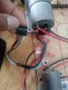
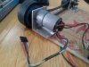
hi guyz!!..........i have a dc motor with encoder on it but i dont know the wiring of the encoder and the part no of motor and encoder is also not there can any one tell me the which wire is for what purpose ??? it is a 6 wire encoder..
 

Attachments

  • IMG_20140618_154536131 - Copy.jpg
    IMG_20140618_154536131 - Copy.jpg
    115.5 KB · Views: 175
  • IMG_20140618_154558616 - Copy.jpg
    IMG_20140618_154558616 - Copy.jpg
    177.2 KB · Views: 172
This is pure guess and speculation on my part. Most of these small DC motors used in robotics and other task are similar. So let's try something. Hopefully you have an ohmeter.

I see your red and black wires connected to the motor independent of the connector. Those are likely the motor power. You also have a red and black on the connector. See if they are in fact the same points electrically. Measure from the red independent to the red on the connector. Are they the same point electrically measuring less than an ohm? Now do the same for the black leads, are they the same? Should this be true it's a good start. So:

Red + Motor Power (could be 6 to 12 volts DC) actually I haven't a clue).
Black - Motor Ground

Green = Encoder ground
Blue = Encoder power supply (3.5-20 V) again a guess here.
Yellow = Encoder A output
White = Encoder B output

Most of these little motors use a Hall Effect Transistor output. The A and B encoder outputs are used to determine the motors rotational speed as well as direction. The encoder outputs will be pulses around the DC level of the encoder power supply voltage and one output will lead the other by about 90 degrees. So if output A leads output B by 90 degrees rotation might be CW (Clockwise facing the shaft) or if B leads A the reverse would be true.

Next, that motor has a large head on it lending me to believe it has a gear head. So the actual motor shaft speed is not the output speed. This is where you need to know the gear ratio. For example the rotation of a magnetic disk at the back of the motor shaft signals the hall effect transistors. This Hall effect encoder has a resolution of 48 cpt for the motor shaft, which results in 1633 cpt for the output shaft. Just depends on the gear ratio which must be determined or known. The CPT is the Counts or Pulses per Turn. Having the actual manufacturers part number and name would be a big help. Look for any reference to a gear ratio, anything at all on the motor?

Again, this is a very rough guess on my part but where I would start. The A and B outputs are encoded outputs so then they must be decoded to use the information they provide.

Ron
 
Status
Not open for further replies.

Latest threads

New Articles From Microcontroller Tips

Back
Top