Continue to Site

Welcome to our site!

Electro Tech is an online community (with over 170,000 members) who enjoy talking about and building electronic circuits, projects and gadgets. To participate you need to register. Registration is free. Click here to register now.

  • Welcome to our site! Electro Tech is an online community (with over 170,000 members) who enjoy talking about and building electronic circuits, projects and gadgets. To participate you need to register. Registration is free. Click here to register now.

Motor Drive

Status
Not open for further replies.

YAN-1

New Member
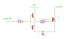
Hi everyone. I've been trying to drive a unipolar stepper motor for a long time now! The motor runs perfectly for a while and then the MOSFETs get damaged. :( I have tried everything I know but I still cannot figure out why this is happening. The motor operates at 2 amps. I'm driving it through a PIC 16F876A and I'm using 4 IRF530 MOSFETs for the phases and 4 FUF 5407 diodes as freewheeling diodes. I'm using heat sinks for the MOSFETs and although the motor is supposed to run at 4 volts (in order for the 2 amps to flow), I am using a supply voltage of 12 volts and a PWM signal to control the current through a current-sensing resistor.

Everything works fine for a while and then all of a sudden, the motor is behaving in a weird way (it vibrates and stalls) and so I check the MOSFETs and they're damaged! I've spent a lot of money on MOSFETs so far. The IRF530 is more than enough in terms of current, voltage, and time response. I asked an engineer at uni and he told me that the only possible explanation could be the dv/dt characteristic of the MOSFET. He suggested that I add a snubber circuit. I know that is an RC circuit but I'm not sure how to select its parameters, how to calculate dv/dt of my circuit, and how to make sure that's the problem in the first place. Please help me out as I am running out of time, hope, and allowance!
Thanks a lot.

Nichola V. Abdo
 

Attachments

  • drive.jpg
    242.3 KB · Views: 1,080
Well When you turn of a power device there will be a voltage overshoot due to the stray inductance (reminds me I need to write that Power electronics cookbook for this forum...)

Now since you have 100V FET's you are not avalaching them at turn-off.

AS to the dv/dt maybe BUT you really dont want a Snubber, all a snubber does is moves the problem to somewhere else (admididly the snubber is design to take the power)

I would be more concerned abt the gate-drive myself, poor gate-drive and EXTREAMLY poor power-layout result in last-minuit fixes that require Snubbers (they are really only fitted these days due to other design problems)


So first question

1) what does the gate-drive cct for the 4 FET's look like, you will want something that can source a good couple of Amps

2) how tight are all the electronics (power switches and diodes!!!!) you need to get everything as close as possible to reduce stray inductance since the stray inductance will then present itself as a dv/dt issue (resulting in snubbers being required)

ALso do you have a Capacitor at your DC-link? even if it comes from a battery you relly want to have a nice big capacitor
 
Styx said:
Well When you turn of a power device there will be a voltage overshoot due to the stray inductance (reminds me I need to write that Power electronics cookbook for this forum...)

Now since you have 100V FET's you are not avalaching them at turn-off.

Well I didn't understand that. Can you please elaborate on what I should do?

As for the gate drive, I am driving the gates through opto-couplers that are switched by the PIC pins and are used to pass the 5 Volts to the MOSFET gates. Sometimes I drive the gates from the PIC directly. In either case, there are of course pull-down resistors (10 k ohm). I will add the capacitor to the input of the system. Do you recommend changing the MOSFET? As for the gates, I didn't know I was supposed to provide them with that much current.
 
Oh and as for the switching frequency, the sequence output to the gates is issued by the PIC at 1 ms intervals (just 1 kHz!) which means that a certain MOSFET gets switched on for 1 ms once every 4 ms. But during the 1ms period, it gets switched on and off either by a certain PWM signal in order to control the current or just normal turning on and off by monitoring the current as well. In either case, it says in the datasheets that the IRF530 can handle switching rates up to 1 MHz. And they are getting damaged even if I don't use current control (i.e. if I just output a 1 to the gate for 1 ms).
 
YAN-1 said:
Styx said:
Well When you turn of a power device there will be a voltage overshoot due to the stray inductance (reminds me I need to write that Power electronics cookbook for this forum...)

Now since you have 100V FET's you are not avalaching them at turn-off.

Well I didn't understand that. Can you please elaborate on what I should do?

As for the gate drive, I am driving the gates through opto-couplers that are switched by the PIC pins and are used to pass the 5 Volts to the MOSFET gates. Sometimes I drive the gates from the PIC directly. In either case, there are of course pull-down resistors (10 k ohm). I will add the capacitor to the input of the system. Do you recommend changing the MOSFET? As for the gates, I didn't know I was supposed to provide them with that much current.

Well its all to do with stray inductance. Every single piece of wire, track, bond wire has it and it is the bane of power-electronics

You have the load represented as an inductor (as it is) and the free-wheel diodes to allow a path for the current to carry on flowing.
However, the load is not going to be the only source of inductance. The critical stray inductance is the inductance from the DC-link capacitor and the top Diodes & load(needs to be low) and also the stray inductance between the diode and the FET

You might think it is only a few cm but it is critical. You cannot get rid of all of it becuase of the stray inductance from the bond wires within the FET package, but you can try to minimise any extra


This stray inductance will try to keep the current in it flowing when you try to turn the FET off, it manifests itself as a voltage overshoot at the drain of the FET (or collector of a BJT/IGBT)

THis overshoot will always occur (hence why you need higher voltage switches then your power rail). You want to keep it to a minimum because the higher it is the higher the turn-off losses are and in worst case you over-voltage the device and it avalanches.


As to the gate-drive (or lack of in this case) decent FET driving is critical (yes FET's can take that much, the speed that you switch them is dependent on decent gate-drive)


What it sounds like is happening is you are driving the FET-gate directly from the PIC which is a digital signal output and has limited output source/sink current capability, so you try to switch hte FET on with a low-current and it will just take a looooong time to turn-on/off and thus will sit in its active region (volts and amps at the same time) and dissipate power, and cook itself to death

By providing decent gate-drive the gate can be charged up and discharged alot better. It could take 1A but since this is from a 5V more then likely 100mA max (gate res dependant), which is a order of magnitude greater then what you have atm

The gatedrive doesnt have to be complicated, just something that can source current (to charge the gate) and sink current (to discharge the gate)


So from this piccy the NPN will provide a better current-source to the FET-gate to turn it on fast, and the PNP will provide a better short to ground to discharge the FET-gate, teh gate resistor is there to stop you burning it out 100R is chosen to give a gate current of 50mA but you might want lower resistance (dont go below 50R though). THE BJT's need to be rated for pulse at least 100mA )

The PIC might be able to source 23mA but can it sink that as well?

Also 5V seems very low, what is the threshold voltage? that changes w.r.t. how much current is flowing through the FET, so you might want to raise the gate potential

The datasheet says the threashold voltage is 4V MAX for a drain current of 250uA but you have a current of 2A, this datasheet is lacking in the curve department so you cant see what the threshold characteristic is like w.r.t. load current (sloppy) BUT since they are saying it can take a gate potential of +/-20V I would be tempted to drive it with +/-10V to ensure saturation
 

Attachments

  • gatedrive.png
    gatedrive.png
    2.6 KB · Views: 1,101
So since I have a 100 V FET, I shouldn't worry about getting a larger one as long as I keep my wires short? I mean the problem is not in the FET itself in terms of its specs?
 
YAN-1 said:
So since I have a 100 V FET, I shouldn't worry about getting a larger one as long as I keep my wires short? I mean the problem is not in the FET itself in terms of its specs?

yer the FET isnt the limiting factor in terms of spec
 
please read my prev-prev post, edited it and added extra info
 
Well thanks a lot. I've downloaded many articles related to gate drive and I'm reading. But I just have one question. If the MOSFETs were never actually fully turned on, how come the power supply always indicated a draw of full current and the motor turns (for a while ofcourse before the FETs are damaged)? Is it because it never reaches the full ON state but it is acting as an amplifier now (linear region) and it passes the current but yet heats up a lot?
 
YAN-1 said:
Well thanks a lot. I've downloaded many articles related to gate drive and I'm reading. But I just have one question. If the MOSFETs were never actually fully turned on, how come the power supply always indicated a draw of full current and the motor turns (for a while ofcourse before the FETs are damaged)? Is it because it never reaches the full ON state but it is acting as an amplifier now (linear region) and it passes the current but yet heats up a lot?

Yup you got it!!! IF the device is never fully ON or it take longer to turn-ON (due to inadiquate gate-drive) then it sits in its active region and can be viewed as a veriable resistor

Current can still flow, its just there is also a voltage across the FET at the same time, a voltage that is alot higher then it saturation (IE hard-on) voltage and thus is dissipates alot of power
 
Well, I read some articles and I'm getting the TC4427 MOSFET driver to drive the gates instead of using a transistor pair. This IC can provide a peak current of 1.5 Amps at 18 Volts to the gate. I did some calculations and if I'm right, my MOSFET needs around 0.43 amps of peak current for the gates to switch on so this IC should do the job at a VGS of 12 volts. Should I place a limiting resistor between the IC and the gate since it can provide me with more than I need or will the MOSFET charge faster and stop drawing current and it'll be ok? As for the inputs of the driver, it will be switched on and off through the opto-couplers. The opto-coupler will take the signal from the PIC and will pass on the PWM to the driver. That should work, right? Thanks a lot.
 
YAN-1 said:
Well, I read some articles and I'm getting the TC4427 MOSFET driver to drive the gates instead of using a transistor pair. This IC can provide a peak current of 1.5 Amps at 18 Volts to the gate. I did some calculations and if I'm right, my MOSFET needs around 0.43 amps of peak current for the gates to switch on so this IC should do the job at a VGS of 12 volts. Should I place a limiting resistor between the IC and the gate since it can provide me with more than I need or will the MOSFET charge faster and stop drawing current and it'll be ok? As for the inputs of the driver, it will be switched on and off through the opto-couplers. The opto-coupler will take the signal from the PIC and will pass on the PWM to the driver. That should work, right? Thanks a lot.


Yer MOSFET driver chips are great for these kinda low-level stuff.
400mA should be plenty to turn the device on fast and with the higher gaqte-voltage it should saturate nicely as well
I am a bit confused you say the chip is 18V but then talk abt a Vgs of 12V

Have you set it to provide 12V of something (via its supply rail).
Apart from that looking good.

Gate-drives is one of those things that is overlooked, esp by software and low-level ppl, its not until you apreaciate the switching times involved and what is needed to charge the cap that you then start seeing the benefits of gate-drives

They get alot more complicated as well ;)
The simplest one that I use is a DC:DC converter, opto and a FET-driver
getting onto 5W gateboard with DeSat control, local undervolts and ACtive gate control for performance shaping
 
Styx said:
I am a bit confused you say the chip is 18V but then talk abt a Vgs of 12V

Have you set it to provide 12V of something (via its supply rail).
Apart from that looking good.

Well the IC takes a voltage range between 4.5 to 18 Volts. I'll be using 12 Volts since I already have that at the input of my voltage regulator which outputs 5 volts to my logic circuit. The peak current of the IC is 1.5A at 18V so it'll be around 1 Amp at 12 Volts assuming linearity! Do you think that I should limit that current through a series resistor? Anyways, the frequency of the motor control signals is such that each pulse is on for 1 ms. During that 1 ms, the ON pulse is really a PWM signal with a frequency of 4 KHz (so that 4 pulses are given to it withen 1 ms) with a duty cycle that varies according to closed-loop control through current sensing. Does that make any sense?

To be honest, I'm a bit scared :oops: I'm gonna get the driver tomorrow and will (once again) build the cct. If the MOSFETs get damaged this time, I don't know what I'll do! Is there any way by which I can test the gate drive for, say, one phase only or do I have to be running the whole thing for me to see the real thing because of the autotransformer effect of the unipolar stepper motor? Thanks again.
 
YAN-1 said:
Styx said:
I am a bit confused you say the chip is 18V but then talk abt a Vgs of 12V

Have you set it to provide 12V of something (via its supply rail).
Apart from that looking good.

Well the IC takes a voltage range between 4.5 to 18 Volts. I'll be using 12 Volts since I already have that at the input of my voltage regulator which outputs 5 volts to my logic circuit. The peak current of the IC is 1.5A at 18V so it'll be around 1 Amp at 12 Volts assuming linearity! Do you think that I should limit that current through a series resistor? Anyways, the frequency of the motor control signals is such that each pulse is on for 1 ms. During that 1 ms, the ON pulse is really a PWM signal with a frequency of 4 KHz (so that 4 pulses are given to it withen 1 ms) with a duty cycle that varies according to closed-loop control through current sensing. Does that make any sense?

To be honest, I'm a bit scared :oops: I'm gonna get the driver tomorrow and will (once again) build the cct. If the MOSFETs get damaged this time, I don't know what I'll do! Is there any way by which I can test the gate drive for, say, one phase only or do I have to be running the whole thing for me to see the real thing because of the autotransformer effect of the unipolar stepper motor? Thanks again.

Ha, thats what I love about power electronics, now matter how many times I have done something there is always that "what if"

The FET drivers dont work linearly like that, ie supply less voltage the current capability will come done by that ratio. All a FET driver really is is a PUSH_PULL output stage (like the BJT one I drew out) and at 18V it can source 1.5A, at 10V it will be able to source 1.5A peak. What current it actually supply's is based upon the gate-resistor

the FET-driver just says what the max amps it can source is.

You will definitly need a gate-resistor otherwise you will burn out the gate-region if you are unlucky, or set up an oscillator if you are unlucky

So for your 400mA you would need a gate resistor of 30R (assuming it is +12 and not +/-12V. It is a shame that FET doesn't have detailed curves to show its characteristics


As to safety can you limit the current from the main power-supply (feeding the DC-link_ that will at least allow you to switch. Also it might be an idea to measure the temp of the FET's via a thermal couple just to see if the problem is still occuring (the FET's can take it for a short time just not long term)

You do have the FET's on a heatsink dont you? even if they are switching correctly, they will still dissipate power (switching and conduction)
 
I'm quoting an application note by Microchip:

"MOSFET drivers are rated by the driver output peak
current drive capability. This peak current drive capability
is generally given for one of two conditions. Either
the MOSFET driver output is shorted to ground or the
MOSFET driver output is at a particular voltage value
(usually 4V, as this is the gate threshold voltage at
which the MOSFET begins to turn on and the Miller
effect comes into play). The peak current rating is also
generally stated for the maximum bias voltage of the
part. This means that if the MOSFET driver is being
used with a lower bias voltage, the peak current drive
capability of the MOSFET driver will be lower.

....The equation has produced a peak drive current
requirement of 0.5A. However, the gate drive voltage in
the design parameters is 12V, and this must be taken
into account when selecting the appropriate driver. For
instance, if the driver you are selecting is rated for 0.5A
at 18V, the peak output current at 12V will be less than
0.5A. For this reason, a driver with a 1.0A peak output
current at 18V would be chosen for this particular
application.
Any external resistance between the MOSFET driver
output and the gate of the power MOSFET will also
need to be taken into account, as this will reduce the
peak charging current supplied to the gate
capacitance."

But where am I gonna find such small-value power resistors!

And yes, I do have heat sinks. I got that part right!
 
Well ok yes when connected directly to the MOSFET the maximum output current of the driver-chip will be related to the supply voltage, I was concidering the use of the gate-resistor

That aside you have already chosen your operating point
12V, 400mA (that the chip can deliver) and that 400mA will be set via the gate-resistor.

as to power...
remember it doesn't have 400mA of continuos current, The gate-resistor will only dissipate power during the charging and discharging of the gate capacitance (ie during turning on and turning off)


So from the datasheet the input capacitance is 1300pF
From your operating point the gate-resistor needs to be 30R


So you will be charging the gate-capacitance from 0V to 12V when turning on and 12V to 0V when turning off


For simplicity assume charging/discharging curve is standard exponential curve of a capacitor (in practice it isn't due to the Millar effect


I = V/R* ( exp(-t/RC) )


Now the time it takes for that curve to reach 5 times constant is going to be insignificant to your switching time so:

The instantious power in the gate resistor is IR
P = (V*V/R)*( exp(-t/RC) )

now if we integrate that over 5 time constants worth we will get the energy needed to switch the gate on/off

E = -CVV(-1 + exp(-5) )

E = 185nJ

Now there is a turn-ON and turn-OFF event in one PWM period so the total energy needed to turn the FET on once and off once is twice that


E = 371nJ


Now the clever bit.
The power is basically that energy time the switching freq. You say that the switching freq is 4KHz ???
Are you sure the switching freq seen by the FET's is 4KHz?

so the power dissipated in the gate resistor is: 371nJ x 4000 = 1.5mW

not much of a resistor is it.


If you could go through my maths (figures and my equations) just to check my calculations (late here)
 
Hi! Well thanks a lot for your help. I went over the figures and they're correct. However, turns out that I might have made a mistake in my previous calculations and I ended up getting an 18-ohm resistor for the gates and I somehow now get around 350 mA. I also changed the operating frequency because I just couldn't get to the PWM frequency that will not draw high current and will not cause the motor to stall or vibrate at the same time. Anyways, I still got current control through measuring the voltage drop across a resistor that is in seires with all the phases and whenever the current goes over the ratings, I switch it off for 8 microsec and when it falls below that, I turn it on for 30 microsec. So I'm not sure about the frequency at which the MOSFETs are being switched on or off but I'm sure it can be calculated from the RL circuit of a certain phase. The bottom line is, it's working so far! I just hope it keeps up like that and no MOSFETs get cooked in the near future because I just can't handle it now! I just never knew there was so much behind MOSFET drive to take into consideration. Thanks again.

Nichola Victor Abdo
 
Hi! Well thanks a lot for your help. I went over the figures and they're correct. However, turns out that I might have made a mistake in my previous calculations and I ended up getting an 18-ohm resistor for the gates and I somehow now get around 350 mA. I also changed the operating frequency because I just couldn't get to the PWM frequency that will not draw high current and will not cause the motor to stall or vibrate at the same time. Anyways, I still got current control through measuring the voltage drop across a resistor that is in series with all the phases and whenever the current goes over the ratings, I switch it off for 8 microsec and when it falls below that, I turn it on for 30 microsec. So I'm not sure about the frequency at which the MOSFETs are being switched on or off but I'm sure it can be calculated from the RL circuit of a certain phase. The bottom line is, it's working so far! I just hope it keeps up like that and no MOSFET’s get cooked in the near future because I just can't handle it now! I just never knew there was so much behind MOSFET drive to take into consideration. Thanks again.

Nichola Victor Abdo


Good to hear. Hardly anyone appreciates gate-drives circuits. There have been a few threads here where I have honed in on the gate-drive (or lack of) as the source of the problem.

Yes a MOSEFET is a voltage controlled switch and in some cases you can just say “put 5V onto it and it will turn on”. BUT when real current (as opposed to low-level signal current) starts to flow such a view is no longer that simple esp if the driving cct has a current-limit (like a PIC at 23mA – VERY BAD!!!).

AS to my calculations they were a bit off, I have attached a spreadsheet I use at work for gate-resistance power calculations. THIS is for an IGBT but is still valid for MOSFET’s, it’s just my gate-resistor is extremely low for what you would use for a FET. Either way the power handling of the gate resistor is still very low, you will prolly have use for this sheet in future though.

Sounds like you have the problem that kicked off this thread sorted which is good


And well this has given me the motivation to write a basic power electronic cook-book for this forum, just covering the basics and the common things that are overlooked
 

Attachments

  • gateres.xls
    451 KB · Views: 147
I just don't see, how he gets to that equation:

For simplicity assume charging/discharging curve is standard exponential curve of a capacitor (in practice it isn't due to the Millar effect


I = V/R* ( exp(-t/RC) )


Now the time it takes for that curve to reach 5 times constant is going to be insignificant to your switching time so:

The instantious power in the gate resistor is IR
P = (V*V/R)*( exp(-t/RC) )

now if we integrate that over 5 time constants worth we will get the energy needed to switch the gate on/off

E = -CVV(-1 + exp(-5) )

Could someone explain it and maybe write it in Equation editor or MathCAD e.a. for simplicity?
 
Status
Not open for further replies.

New Articles From Microcontroller Tips

Back
Top