Continue to Site

Welcome to our site!

Electro Tech is an online community (with over 170,000 members) who enjoy talking about and building electronic circuits, projects and gadgets. To participate you need to register. Registration is free. Click here to register now.

  • Welcome to our site! Electro Tech is an online community (with over 170,000 members) who enjoy talking about and building electronic circuits, projects and gadgets. To participate you need to register. Registration is free. Click here to register now.

Motor Controlling Circuit?

Status
Not open for further replies.

adamthole

New Member
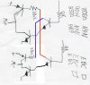
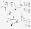
I was looking at the circuit board of an old toy that has a small motor that goes forward and reverse. I drew out the schematic of the circuit and I don't recognize it. I would have thought they would have used an H-Bridge to control the motor going forward and reverse. Can anyone explain to me why they used what I have attached? Which would be better the attached or an H-bridge?

Thanks!
 

Attachments

  • schematic.jpg
    schematic.jpg
    75.2 KB · Views: 171
Last edited:
What is the extra transistor on each side for? So the micro controller only has to deal with two inputs instead of four, or is there a performance gain?
 
I can't read anything in that drawing, but the two transistors are probably to amplify the signal so since the uC is not enough to drive the BJT. And since there are only two, isntead of 4, I would also think that it's reduce the H-bridge inputs to two (forward, reverse, no brake).
 
I think you have the PNP transitors mixed up between the M+ and M- sides. The way it is drawn, the only thing that would happen is some hot transistors and a dead battery. This is what I think you really have:
 

Attachments

  • schematic.jpg
    schematic.jpg
    142.1 KB · Views: 153
Status
Not open for further replies.

New Articles From Microcontroller Tips

Back
Top