threewheeler7
New Member
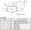
I am working on a h-bridge motor controller, driven from a uC. the uC sends two lines for direction and has a PWM output. now, i have the controller running for what i need, but i need a good h-bridge, i have a few ta72915 SIP bridge drivers, depending on how easily i can find more, these may be what i use in my final design, if not, it will be something close. but for now, i will be using this chip just because i have it. basically i need to know, how i run this PWM'ed. ie. where dose my PWM line from my uC go? i have included 2 screen shots from the data sheet, the pin descriptions, and the sample circuit.
")