I posted a request to see if someone can help me produce an IC to control a motor. I need the motor to move clockwise for 15 secs and then counter clockwise for 15 sec. The machine I have is currently controlled by 2 relays; 2 delay switches, and a cammed micro switch to toggle the relays (CW/CCW). The current system is unreliable with solder fatigue and the switch goes bad yearly.
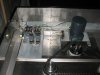
I attached a picture of the current control to help. The power is provided via a separate timer that I set for a given period of time. When the timer goes off, the system shuts down. This part of the control is fine.
There are five sets of components in picture that I assume would go away:
2 relays in the back; micro switch on left; 2 1 sec delay switches; and the capacitor next to the motor.
Not a student. Any help, recommendations, and/or options would be appreciated. If the price isn't too bad, I can even pay someone to give me something that works!
Thanks in advance,
Tom
advancesigns@msn.com