Electro Tech is an online community (with over 170,000 members) who enjoy talking about and building electronic circuits, projects and gadgets. To participate you need to register. Registration is free. Click here to register now.
Welcome to our site! Electro Tech is an online community (with over 170,000 members) who enjoy talking about and building electronic circuits, projects and gadgets. To participate you need to register. Registration is free. Click here to register now.
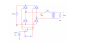
I don't know much about power electronics, but why the buffer after the inverter following the VSW source? This would put a delay in your bridge. What I mean is one FET would be on before the other is off.
You need a separate gate drive voltage referenced to the source pin for each top MOSFET (rather than referenced to ground). The voltage difference between gate-source is what controls the MOSFET, and for top MOSFETs, their source voltage is not constant and is not fixed at ground.
But drive circuits for this special circuit must be able to accept ground referenced inputs (like from MCU), but output a voltage that has a floating reference to control top MOSFETs because their source pin voltage is not always at ground.
You don't need special floating gate drivers if you use 2 PMOS and 2 NMOS. You still need gate drivers if you want to switch the MOSFETs at high frequency for PWM, but you can use regular ground-reference gate drivers if you use 2 PMOS and 2 NMOS.
For top-side PMOS, if maximum inverter voltage is larger than maximum gate voltage on PMOS you need an extra series-connected pull-down transistor and resistor with a pull-up zener diode to drive gate. THis is to protect MOSFET gate from overvoltage and undervoltage when using simple pull-up/pull-down switching for MOSFET gate. If maximum gate voltage is larger than maximum inverter voltage used, simple pull-up resistor and pull-down transistor works just fine.
Using 4 NMOS does make things more difficult, but you get better performance. SOmetimes though, this performance is not worth the size, expense or complexity of circuit. Easiest way if you want to use 4 NMOS is to use "bootstrap gate driver IC" to drive top NMOS. Often they also have built-in drive for lower NMOS too.
DK: since he does not state what the operating voltage is, he still need translators and a high side supply.
khatib: of course you can as long as you are using a normal PWM system you do not need floating supplies since you can use simple bootstrap circuits for the floating supplies that charge caps floating on the outputs that charge up through diodes when they are pulled down.
This site uses cookies to help personalise content, tailor your experience and to keep you logged in if you register.
By continuing to use this site, you are consenting to our use of cookies.