Continue to Site

Welcome to our site!

Electro Tech is an online community (with over 170,000 members) who enjoy talking about and building electronic circuits, projects and gadgets. To participate you need to register. Registration is free. Click here to register now.

  • Welcome to our site! Electro Tech is an online community (with over 170,000 members) who enjoy talking about and building electronic circuits, projects and gadgets. To participate you need to register. Registration is free. Click here to register now.

MOSFET that is saturated without gate triggering !!

Status
Not open for further replies.

BGAmodz

Member
Hello everyone here .

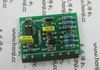
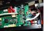
So today i have to deal with a card that belongs to a ARC welder , this card contains a smaall card .

After analysing the suspected areas responsible for the unit's startup , i have discovered some bad components , but i have trouble with a MOSFET (IRFPE40) , i have removed it put in my test breadboard , and without even triggering it i get drain to source connection as soon as i power on the device .

Is it due to static electricity or maybe a bad MOS ?


Also i found (on the small card ) a probably bad npn transistor (Kec MPS 8050D) giving junctions between collector and emmiter while performing diode test mode, can i replace it with a BC337 ??
 

Attachments

  • v1XCY8A.jpg
    v1XCY8A.jpg
    102.6 KB · Views: 267
  • 0JWng4G.jpg
    0JWng4G.jpg
    82.5 KB · Views: 289
Last edited:
when you test the fet you should 'ground' the gate - i.e. connect it to the source, otherwise there may still be a charge on the gate which will keep it turned on. Or it could be a bad fet.

Also check that there's no continuity between the gate and other pins.
 
THanks mab , i have done a test circuit , and things looks good , what about the Kec mps 8050D transistor , do you think bc337 is a good equivalent for it , i am bad at reading technical specs thats why i ask .
 
Its actually 8050 not 80580 :
Here is the ratings for the two transistors .

BC337 : Ic = 0.8 A , Ib = 50 mA, Vce =45v , Vbc=50v , Veb = 5v .
MPS 8050 : Ic = 1.5 A , Ib = 80 mA , Vce = 25v , Vbc =40v , Veb = 6v .
 
Hi,

When the drain source is energized with the gate open, the capacitance between drain and gate could energize the gate enough to turn the device on. It depends on the drain to gate capacitance and the gate to source capacitance and the rate of change of the supply voltage dv/dt and the highest level of supply voltage Vcc. But once turned on, the MOSFET could stay on for a very long time because there is very little DC drain from gate to source.

This means a gate to source resistance is always necessary at the very least for testing a MOSFET. Then to make sure it can turn on ok, energize the gate separately.
 
This is the circuit i have made :
 

Attachments

  • IRPE40.pdf
    171.4 KB · Views: 168
  • 655465.JPG
    655465.JPG
    82.9 KB · Views: 221
Your circuit has gate to source voltage on the mosfet ALL THE TIME so of course the Mosfet is turned on all the time.
Your switch simply turns the LED on and off.
 
Hi,
a gate to source resistance is always necessary at the very least for testing a MOSFET. Then to make sure it can turn on ok, energize the gate separately.

Why a resistance is necessary , is it for gate source capacitance discharge ???

Your circuit has gate to source voltage on the mosfet ALL THE TIME so of course the Mosfet is turned on all the time.
Your switch simply turns the LED on and off.
Actually i was switching manually the gate .

THis is the actual test circuit i made ..
 

Attachments

  • 655465.JPG
    655465.JPG
    85.4 KB · Views: 271
Last edited:
Since you were manually switching the gate then why did you post a completely different circuit before?
Your new schematic shows that the switch can connect the gate to the source then the Mosfet MUST turn off.
 
Since you were manually switching the gate then why did you post a completely different circuit before?
Your new schematic shows that the switch can connect the gate to the source then the Mosfet MUST turn off.

Sorry for that , was a bit confused .

The mosfet turns off when i connect the gate to ground, and turns on when i connect it to +vcc , this how i checked it , and it actually acting the way it shoud , so everything's good for now .

I need to dig more to find why the Welder does not turn on .
 
Why a resistance is necessary , is it for gate source capacitance discharge ???

Yes

A BD139 is rated for 1.5a, but check the hfe before bunging one in, the '139 is an old device and doenst have high gain.
 
Why a resistance is necessary , is it for gate source capacitance discharge ???

Hi,

Well if the gate is already charged, yes, and that will turn the MOSFET off. If the gate is not charged yet it can keep it from getting charged during turn on.

The attached circuit is a better circuit for basic testing, although for that MOSFET you have there it may be better to check it with a little more drain current...that's up to you though.
 

Attachments

  • MOSFET-Test-1.gif
    MOSFET-Test-1.gif
    176.3 KB · Views: 300
Hello,

Thanks MrAl , but why did you put a 10k resistor on the groud path ???


That's the resistor to ground that we've all been talking about. You need that to turn the MOSFET off, and keep it off when the button is not pressed.
 
Status
Not open for further replies.

Latest threads

New Articles From Microcontroller Tips

Back
Top