Continue to Site

Welcome to our site!

Electro Tech is an online community (with over 170,000 members) who enjoy talking about and building electronic circuits, projects and gadgets. To participate you need to register. Registration is free. Click here to register now.

  • Welcome to our site! Electro Tech is an online community (with over 170,000 members) who enjoy talking about and building electronic circuits, projects and gadgets. To participate you need to register. Registration is free. Click here to register now.

MOSFET switch design

Status
Not open for further replies.

newbie73

New Member
hi all, i have a design for a MOSFET based switch, its for a basic pulse motor im making but i need a good eye to look over the circuit design and let me know if its good and what the resistor values should be.

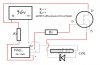
I would really appreciate any help with this as its my first attempt in MOSFET's. I plan on using a 36v power supply (batt dc) the trigger is a hall effect IC (A1301 Hall effect sensor)

i want to dump the 36v through the coil but i need to protect the rest of the circuit, i dont want to use a reed switch or relay as from the data sheets the hall ic and MOSFET can switch faster, giving me more RPM..well i think so anyway, if im wrong please let me know.

anyway here is the circuit, please feel free to amend where its needed.

again thanks for the help
 

Attachments

  • trigger circuit with MOSFET.jpg
    trigger circuit with MOSFET.jpg
    69 KB · Views: 732
Put you load from the + of the 36V power supplyand the drain of your fet. The source is connected to the 0 volts line.
Try it then again.
 
That won't work, the hall effect will smoke because its supply voltage rating is exceeded and if the gate voltage is 6V the MOSFET will just get hot and there won't be enough current through the coil to actuate it.

I don't see how you're getting 6V for the hall effect, a simple resistor won't do because the hall effect's current can vary. You need a linear regulator.

The MOSFET configured as a common source follower so with 6V at the gate the voltage at the source will be 1V to 4V (depending on the resistance of the coil and the threshold of the MOSFET); much too low for the relay to work.
 
cheers Hero999, im glad i didnt just start making this one up, frying a ton of hall's. i have very limited knowledge of electronics, the control system im using at the mo is a 6v suppy hall effect and power pnp transistor set up which woks fine.

I need to up scale the whole motor as i want to use it to drive my bicycle. a normal pulse motor is great but no real usable torque, the design i have uses 3 air coils pushing against 3 N52 neo magnets. even with 6v through the coils i am getting enough torque to get movment, but not much. i did try a reed switch set up and with 36v the torque is massive and the motor has no problem pushing me along a about 15mph.

I just dont want to use reed switches anymore. i am lost on the liner reg you mentioned and would have to spend a ton of time getting my head round it...is there any other way i can pulse the coils at 36v and still have a hall's + transistor / MOSFET system. a basic circuit would be good. I did think of having the hall powered by a seperate 6v supply with just the out going to the gate of the MOSFET, i just need to get the MOSFET to switch and allow the 36v to flow through the coil?????

any help would be good, cheers all
 
Status
Not open for further replies.

Latest threads

New Articles From Microcontroller Tips

Back
Top