I would like to use the V+ pin of a MAX232 as a ~10V signal voltage. The signal goes to a high impedance input pin of an IC, so there is very little current draw. I need the signal to stay greater than 8.5V. I read in the MAX232 datasheet that as little as 10mA will drop the voltage on V+ to below 8.5V, so I'm trying to be very sensitive to how much current I'm sourcing from V+.
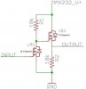
I need to be able to switch the signal on and off, so I put together a n-channel/p-channel switch, as shown in the attached image. Using 10k resistors, I'm calculating that there won't be more than about a milliamp drawn from V+ at any time. The input to the n-channel MOSFET will be 0V to 5V from a uC. I just wanted to make sure that I'm not overlooking something before I move forward with my design. Any input would be appreciated. Thanks!
EDIT: Oops! Just realized the symbol for my P-Channel is upside-down. Ignore that") .
.
I need to be able to switch the signal on and off, so I put together a n-channel/p-channel switch, as shown in the attached image. Using 10k resistors, I'm calculating that there won't be more than about a milliamp drawn from V+ at any time. The input to the n-channel MOSFET will be 0V to 5V from a uC. I just wanted to make sure that I'm not overlooking something before I move forward with my design. Any input would be appreciated. Thanks!
EDIT: Oops! Just realized the symbol for my P-Channel is upside-down. Ignore that
.Attachments
Last edited:
