Continue to Site

Welcome to our site!

Electro Tech is an online community (with over 170,000 members) who enjoy talking about and building electronic circuits, projects and gadgets. To participate you need to register. Registration is free. Click here to register now.

  • Welcome to our site! Electro Tech is an online community (with over 170,000 members) who enjoy talking about and building electronic circuits, projects and gadgets. To participate you need to register. Registration is free. Click here to register now.

Mosfet needed a jump?

Status
Not open for further replies.

MrDEB

Well-Known Member
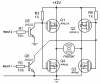
This bridge circuit works great BUT just finished assembling one and Q5 source has / had a weird occurrence.
The circuit works but very dim.
If I short the Gate w the Drain on Q5 the sound gets louder like it should be.
After taking some voltage readings when I touched the probe to the Source of Q5 the project sound level went up to where it is supposed to be.
The source on Q5 is grounded but touching the Source on Q4 nothing changes.
After rechecking Q5 w/ probe it went louder and stays there.
I shut off the supply then turned on again after 5 minutes and project works as desired.
This doesn't sound normal but I checked and rechecked solder connections etc but no explanation WHY the bridge amp now works as it should?
Any suggestions as to WHY? after touching the Source makes it work right.
AGAIN thanks to Audioguru for this great bridge amp.
 
You talk about "dim" and you talk about "sound and its loudness".
But your circuit has no inputs, no light bulb and no speaker.

I designed the circuit to make a DC motor go forward or reverse.

My cvircuit uses Mosfets which are normally enhancement mode.
Your drawing shows a little 2N5459 Jfet that is depletion mode which is completely different.
 
Typo

MrDEB,
As Audio said, you need MOSFETs, not JFETs.

Audio,
What software did you use to draw the circuit?
 
Last edited:
MrDEB,
As Audio said, you need MOSFETs, not JFETs.

Audio,
What software did you use to draw the circuit?
Maybe he talks about this circuit that I drew with
Microsoft Paint program:
 

Attachments

  • H-bridge-Mosfets.PNG
    H-bridge-Mosfets.PNG
    11.2 KB · Views: 208
Thanks Audio,
I assumed that you had drawn the circuit that he posted in Post #1, but he must have drawn it himself - presumably from your circuit posted above.

MrDEB,
What software did you use to draw the circuit?
 
In my post I used DIPTRACE

but here is the link that I should have included the first time

https://www.electro-tech-online.com/attachments/combo-hot-png.44892/
after several hours of the project just sitting w/o power it will still sound as it should LOUD.
I must have maybe discharged the mosfet??
Anyway it works now
The input is a PIC and the output is connected to a piezo tweeter horn.
would love to know why the dang project now works just by placing a DMM probe on the Source pin on the N mosfet.
 
but here is the link that I should have included the first time

https://www.electro-tech-online.com/attachments/combo-hot-png.44892/This is so small that it is unreadable.
after several hours of the project just sitting w/o power it will still sound as it should LOUD.
I must have maybe discharged the mosfet??
Anyway it works now
The input is a PIC and the output is connected to a piezo tweeter horn.
would love to know why the dang project now works just by placing a DMM probe on the Source pin on the N mosfet.
I may be able to explain it if you post a readable circuit.
 
May had discovered the issue.
the Source on Q5 was soldered correctly but the plated through hole is loose. Scraped some of the solder resist coating off and resolder the pin to the scraped area.
 
Status
Not open for further replies.

New Articles From Microcontroller Tips

Back
Top