Electro Tech is an online community (with over 170,000 members) who enjoy talking about and building electronic circuits, projects and gadgets. To participate you need to register. Registration is free. Click here to register now.
Welcome to our site! Electro Tech is an online community (with over 170,000 members) who enjoy talking about and building electronic circuits, projects and gadgets. To participate you need to register. Registration is free. Click here to register now.
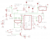
I found a problem with the circuit. R1 has an disconnected pin (should most probably be connected to ground). Thats makes emitter voltage at T2 being around 4 volts all the time, and a little change in PH1 will have virtually no effect.
The Mosfet is shown connected completely wrong, the 5V regulator is missing the important input and output capacitors and the LEDs do not have current-limiting resistors.
You have the load pin hooked up on the counter for some reason but, your ABCD pins are left unconnected or floating so no telling what your going to load. Perhaps you should explain what the circuit is supposed to do.
You show a big long part number for the Mosfet but it does not make sense so datasheetarchive.com could not find its datasheet.
It is drawn as an N-channel Mosfet.
Its gate is usually its input but yours is connected to a motor.
Its source is usually grounded but you show it as the input.
Its drain usually connects to a positive supply voltage but yours connects to ground.
Look at the datasheet for the 7805 regulator to see the important input and output capacitors.
LEDs and laser diodes are diodes. If you do not limit the current then they blow up. Your circuit does not limit their current.
Thanks Audioguru. The laser already has a resistor. It is going to be mounted "off board". Wouldn't R1 work to limit the current for my led? I also fixed the Mosfet ( or at least I think I did).
Mikebits, thanks for pointing that out. I had accidentally connected it to load instead of clear. The circuit is supposed to count the number of times to beam of light between the counter led and the photo cell. When it reaches 3 the motor is supposed to turn off. When the trigger switch is released the counter is supposed to reset to 0.
Load pin should be pulled high. For ABCD pins ground is fine. For the gates I did not see any unused pins. Why are you using obsolete parts for your gates?
Yes, the bubbles indicate that a signal is active low. Also it would help if you spread out the schematic, it is somewhat crowded and hard to read. Just trying to help.
Thanks.
Do you really think that i need filtering capacitors for my voltage regulator? I tried once. I am using a 12v lead acid battery for my supply. The capacitor exploded.
Ceramic disc or ceramic multi-layer capacitors are usually used for voltage regulators. Tantalum capacitors explode. Electrolytic capacitors also explode if they are connected with backwards polarity.
Now the Mosfet is drawn correctly. But its gate and the CLEAR input of the counter "float" without a logic level when the push-button is not pressed. It needs a pullup or pull-down resistor.
This site uses cookies to help personalise content, tailor your experience and to keep you logged in if you register.
By continuing to use this site, you are consenting to our use of cookies.

")