Electro Tech is an online community (with over 170,000 members) who enjoy talking about and building electronic circuits, projects and gadgets. To participate you need to register. Registration is free. Click here to register now.
Welcome to our site! Electro Tech is an online community (with over 170,000 members) who enjoy talking about and building electronic circuits, projects and gadgets. To participate you need to register. Registration is free. Click here to register now.
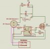
Q2 will never turn on. You have provided two ways of grounding the gate, but have no way of pulling the gate high. Either move the gate resistor so that one is tied to +24V so that the opto-coupler can ground the gate, or vice-versa. 24V may be too high for the gate voltage of the FET, so you may have to add a resistor to create a voltage divider to limit the positive gate voltage.
Note also that the circuit provides an inversion. When the input to the optocoupler is high, Q2 will be off.
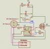
If you want non-inverting, then connect the opto transistor collector to the voltage and the opto transistor emitter to Q2's gate. As Mike noted, you may need a voltage divider to keep the voltage below the opto transistor's and Q2's max. voltage ratings.
If you want the opto to turn Q2 on when there's a signal going into the opto, connect the collector (pin 5) to the + voltage supply and the emitter (pin 4) to the MOSFET gate. You'll need to use a voltage divider because the maximum Vgs of the IRLZ44N is 16V. See my attached changes--the existing R3 plus the new resistor will divide the gate voltage down to 1/2 the supply voltage (12V).
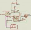
Considering that there is a solenoid in the circuit, I doubt it's high-speed. 100K for both resistors should be fine. Even better, make R4 higher than R3, such as 150K.
But make sure the transistor in the opto can withstand 24V C-E.
Thank you so much crutschow & kpatz for helping me understand the function of the R's. I'll change them to 100 & 150k and try them out.
So far I am only using 12v but please recommend the correct type of Opto for 24 V?
So far on a proto board it's more or less...!
1-The voltage from the Arduino is about 5V but as soon as the Opto is plugged into the circuit, it drops to about 1.5v! Why?
2- However, the Opto is still working fine since on the other side of it utilizing a 12v for now, it shows about 12 with Opto inactive and when the Opto kicks in it drops to 12(source) - (1.5 from Arduino with Opto active) = 10.5!!! Why is the Arduino voltage being deducted from the 12v source?
3- The Mosfet is also functionin but sending just 1V to the solenoids!!!???
What am I doing wrong?
Each solenoid after Muliplexing will get to be on for just a couple of seconds every 15 minutes or so, but like every couple of seconds, a solenoid will get activated.
thanks
p.s.
the led doesn't function or maybe at .8v it just not showing? The solenoid does function with .8v but with no strength obviously.
p.s.s.
I am using a 10k and a 5k in series for the R4, that is not the problem or is it?
Are you measuring at the Arduino output or the optocoupler input? The LED in the opto will drop around 1.5-2V and the resistor will drop the rest. You should still see 5V if you measure between the Arduino output and ground. If not, the Arduino can't provide enough current to drive the opto.
2- However, the Opto is still working fine since on the other side of it utilizing a 12v for now, it shows about 12 with Opto inactive and when the Opto kicks in it drops to 12(source) - (1.5 from Arduino with Opto active) = 10.5!!! Why is the Arduino voltage being deducted from the 12v source?
Where are you measuring the voltage? Across the collector and emitter of the opto? Measure between the gate and source of the MOSFET, since this is the voltage you want. With 15K and 10K resistors and a 12V supply, you should see slightly below 4.8V at the gate with the opto turned on.
3- The Mosfet is also functionin but sending just 1V to the solenoids!!!???
Once again, where are you measuring? Measure across the solenoid coil. If that's where you're seeing 1V, measure across the source and drain of the MOSFET. You should see a high voltage (near 12V) across the source/drain with the MOSFET off, and a low voltage (<1V) with it on.
Also, check your 12V supply to make sure it's producing enough current to power the solenoid. Also, make sure D2 isn't installed the wrong way. It's correct in the schematic (reverse biased) but if you install it the other way, it'll short out the solenoid coil, and probably overheat/blow the diode.
I am using a 10k and a 5k in series for the R4, that is not the problem or is it?
That's fine. Resistors in series add their resistances together.
P.S. What's powering the Arduino? The same power source as your 12V circuit? If the 12V supply can't handle the current, you'll get a voltage drop when the solenoid tries to turn on, causing your symptoms (including the low voltage at the Arduino output, if that is powered by the same supply).
Thank so very much for your kind and detailed observations and recommendations.
I couldn't reply earlier since I had the system down.
Anyhow, I found out the source of the problem, which was due utilizing an IRF Mosfet rather than an IRL! Well someone recommended to add a Zener Diode to the circuit which has helped.
1- I am using a 24 v power I am getting 0 to 14v across the solenoid, meter + probe to L1 left(facing) and - probe to the right L1. Why just 14 and not 24?
2- Arduino at the source is 5V.
3- Mosfet Gate & Source is 0 to 11V with the 24V supply? Why so low?
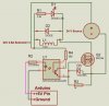
The zener is connected Cathod to U1 pin 4 & Anode to Mosfet's Source(pin #3).
You can increase both R3 and R4 (keep the ratio the same, more-or-less) to reduce the amount of current going through the divider, optocoupler and zener. For example, make R3 10K and R4 3.9K or 4.7K.
You should see approximately 17V at the MOSFET's gate the way the circuit is currently shown, provided that the opto's transistor is fully on. If your zener's breakdown voltage is less than 17V you'll see the zener's voltage at the MOSFET's gate instead of 17V. Whatever you do, you should make sure the gate sees at least 10V (but below the max of 20V) to ensure the FET turns fully on.
With the Zener in the circuit, you could eliminate R3 entirely, as the Zener will drop the voltage as needed. I would raise R4 to something higher like 10k though.
If you're still seeing voltage issues, when the Arduino has the solenoid ON, measure these voltages:
1. Voltage between drain and source of the MOSFET
2. Voltage between pins 5 and 4 of the optocoupler.
Both these voltages should be low (<1 volt) when the circuit is in the "on" mode. They should be high (17-24V) when the circuit is in the "off" mode.
Does the MOSFET get hot when the solenoid is held on for a little while?
I am pretty new to electronics and trying to understand the purpose of the zener.
From the data sheet, if I am reading it correctly, this will only start to conduct at 15v?
With the 24v power source, will this keep the gate of the mosfet at 10volts or less? (I am not accounting for the voltage drops across the opto transistors.)
The Mosfet needs Min. 10V to work and I was told placing the Zener in the circuit will take care of the problem since it's gate was receiving only 5V before.
I am pretty new too and hope to have given you the correct info and hopefully kpatz could contribute here and explain the Zener issue more clearly for us.
This site uses cookies to help personalise content, tailor your experience and to keep you logged in if you register.
By continuing to use this site, you are consenting to our use of cookies.