Continue to Site

Welcome to our site!

Electro Tech is an online community (with over 170,000 members) who enjoy talking about and building electronic circuits, projects and gadgets. To participate you need to register. Registration is free. Click here to register now.

  • Welcome to our site! Electro Tech is an online community (with over 170,000 members) who enjoy talking about and building electronic circuits, projects and gadgets. To participate you need to register. Registration is free. Click here to register now.

More Forum help needed

Status
Not open for further replies.

jerryd

New Member
Electro Tech forum,

I posted about my 555 timer problem in "555 frequency problem"
and thought I had fixed when I changed to a TLC555. Not so.

The 555 frequency is alright but I'm still having power
supply problems.

I think my basic hookup must be wrong.

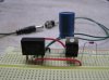
As I stated in my previous post I'm using a 110 to 9 vac
transformer feeding a BR805D full wave bridge and an LM7805C
regulator. Without the regulator hooked up I read 10.47 vac
on the ac pins of the bridge and 4.40 ac volts or 9.05 dc
volts on the other 2 pins.

As soon as I connect the + pin of the bridge to the input pin
of the regulator the dc voltage coming out of the bridge drops
to 8.38. There is a 220uf cap on the input pin of the regulator
and a 10uf on the output pin. The output pin of the regulator
reads only 4.46 volts.

I'm mostly a software guy trying to learn hardware so any help
would be appreciated. I would post the circuit if I knew how.

Thanks,
jerryd
 
From my testing of rectified ac and v-regs a 220uf cap is too small to smooth the ripple and from looking on the Cro the lowest i was able to go down to was 330uf, i would normally use a 470uf to 1000uf and never have a problem.

Try increasing the 220uf cap to double that or greater and i think your problem will go away.

You should also have a small cap like a 0.1uf in parallel with the bigger cap on the input to the v-reg.

Simple things can cause so much trouble and until you have been there its hard to see what difference a wrong value can make.

Pete.
 
Electro Tech forum,

Thanks SABorn for the suggestion.

I put a 1000uf cap on the input pin of the regulator
and the supply seems more stable. Now when I measure
across the positive and negative pins of the bridge I
get 12.5 volts DC even though the AC into the bridge is
only 10.3 volts. Must be the meter is reading RMS.

The only problem I have now is I want to tap off one side
of the AC to get a 60HZ clock but I only measure 5.6 volts
to ground on each AC pin. After I put this through a 1K
resistor there's not enough voltage to reverse bias the
zener diode.

As you can see I'm new at this and struggling.

jerryd
 
Why the zener diode?

Just use a standard silicon diode (1) off one side of the AC and you should get a 1/2 wave rectified signal at 12.5 volt, measured from the diode to ground.
This will give you the 60 hz pulse.

The resistor will only limit current, not voltage.

Rectified DC will normally be 1.4 times higher than the measured AC voltage (suspect your meter dont read AC very well)

Pete.
 
Last edited:
Pete,
Tried a diode(1N4148) to ground off one side of the ac on the bridge
and burned up the diode.

The circuits I've seen on the internet use a resistor and a zener
diode off one side of the ac, so I was just coping.

jerryd
 
You fool!!

The diode DONT go to ground. (that will make a dead short.......smoke....dead diode)

You measure the voltage between the diode and ground.
The diode will be a V+ line and without any capacitor on the line you will get a 60 hz pulse from the line the diode is in.

In other words you have 2 power supplies and ground is common to both of them.

What is it you want to do with the 60hz frequency.

As for photos...scroll down below the reply window and you will seeAttachments click on manage attachments then browse and find the photo file on the computer and click upload.
Thats it......have a go.

Will check back later

Pete.
 
To help you understand better what i was referring to i done a schematic.

Also took some photos of the 2 voltages on the Cro.

line #1 is the bridge rectified and capacitor filtered DC output.......straight line trace.

Line #2 is a single diode rectified (1/2 wave) with no capacitor output.......wave trace.

As you can see the wave swings between V+ and ground at the frequency of the mains supply being 60Hz in your case. (50Hz in my case)

So there is your 60Hz signal you were looking for.

Ground (-) is common to both signals.

Now if you need to drop the voltage of the wave to say.... 5 volt for a TTL circuit than you would place a resistor after the diode to limit the current, and then a 4.7 volt zener diode to ground, this would shunt any voltage over approximately 4.7 volts to ground.

This should then give you a 0 to 4.7 volt wave at 60Hz.

Pete.
 

Attachments

  • Rectified AC.JPG
    Rectified AC.JPG
    32.2 KB · Views: 247
  • 025 small.jpg
    025 small.jpg
    55.2 KB · Views: 162
Pete,

Looked at your schematic and scope pictures and hooked it up
as you've shown. It's a lot more fun when the diode doesn't
go up in smoke.

I get the 60HZ half wave but it's only about 4.7 volts from
the band side of diode to ground measured as DC. Measuring
one side of the AC input to the bridge to ground is only 5.4VAC.
Maybe I don't have the right transformer.

I don't have a scope so it's hard to measure things accurately.
I use my sound card, a voltage divider and some audio editing
software to look at the waveforms. Works OK but no levels.

I'm working with an 11 year old and we have already built
an 8 bit binary counter with a 555, LEDs and a battery.

Next is a binary clock and we wanted to eliminate the battery
and have a more accurate clock.

I've included a picture of my setup.

We seem to be in the same time zone but 50HZ says you must
not be in the states.

Thanks for your time and help so far.
jerryd
 

Attachments

  • P4190068.JPG
    P4190068.JPG
    788.5 KB · Views: 238
I think the voltage reading from the diode is not quite correct as the meter will average the pulse voltage.

What you could do to get a better voltage reading is place a cap from the anode (band) end of the diode to ground and read the voltage across the cap this will tell you what the pulse peak voltage really is.
Remove the cap for 60hz signal.

As for time zones ...no i just keep crazy hours, i am in Australia...hence the 50hz.

Pete.
 
Pete,
You're right, when I put a cap to ground the voltage is 13.5
I added a resistor and zener diode, fed it through a schmitt
trigger and divided it down to 1HZ. Just what I need for the
clock. I think my biggest problem is I don't have a real scope.

Hope I can handle it from here. If not I'll be back.

I'm in Florida USA. I've been trying to convince my wife to
take a vacation to Australia. Fly to Sidney, Cruise up to
the Great Barrier Reef and around New Zealand, and then take
a train all the way to Perth. Probably never happen.

Thanks for the help,
Jerryd
 
Good luck with your project.
Good luck convincing the wife. (at least electronics is predictable)

Your Oz trip you mentioned would take a month or 2 to cover that ground, others often dont realize just how big this place is and how spread out we really our, If you want to go to Queensland than best pack your floaties to be safe. lol.

Pete.
 
Status
Not open for further replies.

Latest threads

New Articles From Microcontroller Tips

Back
Top