I'm not sure if I'm allow to post this...I'm currently working on a project regarding the Miniature Remote Controlled Solar Car and this is my second post. First was the DC/DC Converter (Miniature Remote Controlled Solar Car). Hope this post is allowed.
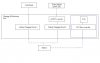
Hi there. I'm currently working on this project and needs help badly. At this point, I will be working on the implementation of the PIC Microcontroller to monitor a few matters and display them using a LCD (Figure Project). These includes the following:
a.) Read current load current drawn from the load, which is a 12V DC motor.
b.) Present the approximate life-time of the battery at that level with that drawn current.
c.) Present the battery level in terms of percentage.
:?: Would like to ask, how do I tap the current drawn by the load and feed it to a Current-to-Voltage Converter before applying it to the PIC microcontroller? At which point shall I tap the current point from? Advice needed.
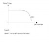
:?: The battery level in terms of percentage, if I were to come out with a look-up table for reference before writing a programme for the PIC microcontroller, do I consider having a table with reference to the voltage or with reference to the current? Reference Figure 1. Advice needed.
Thanks in advance.
Hi there. I'm currently working on this project and needs help badly. At this point, I will be working on the implementation of the PIC Microcontroller to monitor a few matters and display them using a LCD (Figure Project). These includes the following:
a.) Read current load current drawn from the load, which is a 12V DC motor.
b.) Present the approximate life-time of the battery at that level with that drawn current.
c.) Present the battery level in terms of percentage.
:?: Would like to ask, how do I tap the current drawn by the load and feed it to a Current-to-Voltage Converter before applying it to the PIC microcontroller?
At which point shall I tap the current point from? Advice needed.:?: The battery level in terms of percentage, if I were to come out with a look-up table for reference before writing a programme for the PIC microcontroller, do I consider having a table with reference to the voltage or with reference to the current? Reference Figure 1.
Advice needed.Thanks in advance.