Continue to Site

Welcome to our site!

Electro Tech is an online community (with over 170,000 members) who enjoy talking about and building electronic circuits, projects and gadgets. To participate you need to register. Registration is free. Click here to register now.

  • Welcome to our site! Electro Tech is an online community (with over 170,000 members) who enjoy talking about and building electronic circuits, projects and gadgets. To participate you need to register. Registration is free. Click here to register now.

Momentary lockout Solenoid

Status
Not open for further replies.

syntax_x

Member
Hello, New user here with a simple little problem.


**broken link removed**

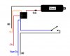
This is the circuit I am working with, it emulates the recoil of a pistol and allows a signal from the trigger to be used. (the black square is a relay..)

The problem I am having at the moment is if the trigger is held down, the solenoid stays engaged, no-brainer right?

So I am trying to make the solenoid receive power for only the duration needed to send it into a fully engaged position.

That way the solenoid recoils before the trigger is deactivated.

I can post up some videos of my progress so far if it helps.
 

Attachments

  • Circut.jpg
    Circut.jpg
    46.7 KB · Views: 629
Firstly, Hi and welcome to the forum. :)

And thank you for posting clear information on exactly what the circuit does and providing your circuit diagram! Lots of first-time posters leave out critical information.

OK, your diode is connected wrong. it should be connected across (parallel with) the solenoid coil, woth the diode ANODE (white stripe) at the + end of the solenoid coil (not the GND end). After that your diode will do it's job, and protect things against the solenoid induced back-EMF spike.

Next, to get the "one shot" result you need, there are a few solutions involving monostable timers, which adds complexity.

You might be able to get away with a simple solution, and just put a large cap (2200uF) in series with the solenoid wire (where you show the diode in post #1).

The cap will make a current pulse while it charges, that will "fire" the solenoid. Then when the cap is charged there is little/no current and the solenoid will drop out. That will require a resistor across the cap, to discharge the cap when the user is not firing. The discharge time will need to be shorter than the time between user firings. Maybe try a 1000 ohm resistor, but have a few values handy if it needs a higher or lower value resistor.
 
Using caps is guessing when the solenoid is fully engaged. I would use something like a simple magnet on the solenoid triggering a reed switch to disable the drive current to the solenoid.

It then makes it a closed loop control system where you definately know the solenoid has engaged.
 
How much current does your solenoid draw at 24V?
 
Hmmm... It seems the Administration team did not like my response...
Lets try again (for the 3rd time...)

Thanks for the warm welcome Mr RB. Nice to have a long time member give me a hand straight up.

Concerning the diode, yes i had it in the wrong spot, the solenoid actually came with 2 diode already inplace, 1 is where you stated.

I have looked into using a 555 timer in momentary mode as a one shot, but im not sure where to start with resistor and cap values, and im pretty sure ill need a pot to tune the response rate.

WTP Pepper, thankyou for your input, its greatly appreciated, but my thoughts were the same as Mr. RB, i feel it would oscillate.
I'm sure with a few flip flops and the magnetic reed it would in theory work, but the solenoid itself has a very violent action and would probably introduce different forms of interference and false inputs.

I WILL post up some links to videos on what i have done thus far.

I would like to add that I am not a student, and that this is not for profit of any kind, except my own enjoyment and maybe others.
If i manage to get this working ill be posting a write-up on how to, and anybody who has helped here will be getting the credit.

Im just a guy with a soldering iron..

Cheers again on the input thus far , ill check the current draw @ 24v right now alec_t.
 
When the solenoid is first engaged the current pull is 1.4 A. If i keep it held it slowly drops past 1.2A. Didn't hold it on any longer than that.
 
What is the foot pedal for?
 
Here's a suggested driver for the solenoid:
SolenoidDriver.gif
 

Attachments

  • SolenoidDriver.asc
    2.9 KB · Views: 277
Hey alec_t, Did you just throw that together for me?

Thanks champ!

2 questions, what is m1?, and what does the pot change?
 
For this ;)

**broken link removed**

Nice machine! I feel a bit silly now, my original comments were with the idea to keep the parts count down, as I thought you were fitting this inside a small device like a laser tag grip.
 
ok so i got all the parts for Alec-t's 555 circuit, just wanted to make sure the caps i bought will work for this.

cap.jpg

**broken link removed**
 
Those caps will be fine.
 
Cheers Roman, I'm pretty happy with the cab myself :)

alec-t, ive built the 555 circuit but I'm pretty sure M1 on your diagram is a transistor. Im not sure what to do there:confused:...sorry.

hopefully i wired the pot up correctly too, i soldered to the outside legs, which is wrong hey, i should of used the middle and left leg i think...:confused:
 
My bad, just wired up the pot correctly, but still unsure of M1.

Also the pot showed it only went to 420k on my multimeter.
 
Status
Not open for further replies.

Latest threads

Back
Top