Continue to Site

Welcome to our site!

Electro Tech is an online community (with over 170,000 members) who enjoy talking about and building electronic circuits, projects and gadgets. To participate you need to register. Registration is free. Click here to register now.

  • Welcome to our site! Electro Tech is an online community (with over 170,000 members) who enjoy talking about and building electronic circuits, projects and gadgets. To participate you need to register. Registration is free. Click here to register now.

Modulated 38khz Infrared Transmitter

Status
Not open for further replies.

kasamiko

Member
Hi,

This is my first time to messed with mobots and planning to make an obstacle avoiding mobot..

I'll be using a TSOP type of infrared receiver salvage from cheap China made DVD players but encounter problems with it...
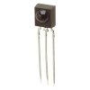
tsop4838-ir-receiver-module-38khz-rc.jpg

The output is HIGH if NOT detecting any infrared signal and goes LOW if infrared is detected..

I tried several circuit of modulated 38khz infrared LED driver but no one works satisfactorily unlike the remote control of my tv..:(

I found out that for this to work, I need to modulate the 38khz signal as well not just a continuous burst of 38khz signal but it most be modulated..100ms ON/10ms OFF or something like that..


Design considerations
For the proper functioning of the Photo module, it is necessary to consider some important aspects.
1. Supply voltage should be + 5 Volts. For this, a 5.1 volt Zener must be connected to the +V pin and ground.
2. A 100 uF capacitor should be connected to the +V pin as a buffer and filter capacitor. This will suppress the power supply disturbances.
3. Carrier frequency should be close to the center frequency of the band pass filter. 38 kHz in the case of TSOP 1738.
4. Burst length must be 10 cycles per burst or more.
5. Between each 10 to 70 cycles, a gap time of 14 cycles is necessary to reset the module.
6. DC lights such as tungsten bulb and daylight affects the functioning of the photo module.
7. Signals from Fluorescent lamps with electronic ballast will affect the working of the photo module.
8. Continuous IR signal (non- pulsed) will disturb the photo module and it will not responds to it.


If you can share a modulated 38khz driver will be greatly appreciated..a 556 or 2pcs of 555 will do..One will be a 38khz and the other is modulating the 38khz...


WBR


RON
 
Last edited:
found this somewhere else in this forum..:D

hope this will work...

**broken link removed**
 
Don't forget to think about the receiver end. The output of the TSOP will also be a square wave. In addition the TSOP's are very sensitive as they are made to detect signals not just on or off.
 
Don't forget to think about the receiver end. The output of the TSOP will also be a square wave. In addition the TSOP's are very sensitive as they are made to detect signals not just on or off.

It doesn't work for me..:(

Change C1 to 0.33uF, R1 to 220R and 33K and I got result...the connection of LED at the output also matters...Cathode to PIN3 and Anode to VCC via resistor not working. But Anode to PIN3 and Cathode to GND via resistor and it works! weird....


For a test transmitter try a remote control. Not all use 38 khz but often close enough.

Well I'm planning to hack a junk remote short 1 button and used it as transmitter if other approach still fails...:(
 
kasamiko,

Check this web site.
**broken link removed**

I just finished building this exact circuit. Just had to
adjust the 556 receiver frequency with the 10K pot and it
works as advertised.

I used a TSOP4838 38KHZ ir reciever and a TSAL6200 High
Output IR LED.

There is a scope picture attached.

Hope this helps.
jerryd
 

Attachments

  • P5210106.JPG
    P5210106.JPG
    868.1 KB · Views: 630
I think I'm suffering with the same problem as that site says...I got my no name infrared LED from electronic store nearby...no brand, no data..:(

Same with my receiver just pulled it out on cheap China made DVD players...

Need to hack some old remote for that LED...

Thanks for the link...:D
 
Last edited:
as IR photo diode, you can use SFH205, in the receiver section.

For transmitter you can salvage any I R led from damaged remotes
 
Last edited:
The transmitter in post 2 should work. What does your receiver circuit look like. Do you have a link or schematic for the obsitcle avoidance circuit?
 
as IR photo diode, you can use SFH205, in the receiver section.

For transmitter you can salvage any I R led from damaged remotes

I can salvage an IR diode on any remote but I can't manage to get hold of this SFH205..:(


The transmitter in post 2 should work. What does your receiver circuit look like. Do you have a link or schematic for the obsitcle avoidance circuit?

The ckt posted on reply #2 when wired according on that schematic don't work for me...i have to modify the first oscillator by changing C1 to 0.33uF, R1 to 220R and 33K but still not satisfied...

BTW see attached image for my sensor connection...

BR
 

Attachments

  • detect.jpg
    detect.jpg
    31.3 KB · Views: 904
What do you expect the output of the sensor to be?

Heal the world by MJ? :D

seriously a LOW for about 500ms...actually it doesn't drop to LOW as in 0 or GND level...but just a slight dip from the 5vdc output...since my sensor is active LOW...pointing a remote controller on it it drops to 3.85 VDC or lower depending on range and its perfect for my application...

There's something badly wrong there - I've used a LOT of different IR IC's and they drop to approaching zero volts - how are you measuring it?.
 
Hi,

This is my first time to messed with mobots and planning to make an obstacle avoiding mobot..

I'll be using a TSOP type of infrared receiver salvage from cheap China made DVD players but encounter problems with it...
.......

I found out that for this to work, I need to modulate the 38khz signal as well not just a continuous burst of 38khz signal but it most be modulated..100ms ON/10ms OFF or something like that..


If you can share a modulated 38khz driver will be greatly appreciated..a 556 or 2pcs of 555 will do..One will be a 38khz and the other is modulating the 38khz...

RON
why don't you use the chip of remote unit itself and wire the few switches you need?
why all this round about way around 555? You would have saved a weeks time by now.
 
Last edited:
The reason I keep asking what you expect is because I don't think the sensors work the way you think they do. If you use the transmitter posted the output of the sensor will be a stream of pulses having about a 500 usec. period. If you point a remote at it you will get about 8 pulses then you must push the button again.
 
I think what he's trying to do, is avoid the automatic gain control (AGC), some receiver modules use. When there is a steady carrier being received, the module drops it sensitivity some, to reduce noise, which would also reduce range. The transmitter needs to be cut off periodically to maintain maximum range.
 
as you develop the robo
you need few additional facilities and it is always better to have decoding of conventional remotes
or adopt dtmf thro ir. so that you would have facility for few additional control signals .
simple carrier detection alone may appear good initially.
thus a modulated Transmitter like conventional DVD remote and a suitable decoder inside is always useful.
 
There's something badly wrong there - I've used a LOT of different IR IC's and they drop to approaching zero volts - how are you measuring it?.


My IR receiver when wired like this and I'll point a TV remote control directly the 5VDC output will NEVER drop to ZERO or GROUND the lowest I can get is about 2VDC which is enough for my needs...

**broken link removed**


Now this circuit with slight modification works ok now...I just change R1 to 220R, R2 to 33K and C1 to 0.47uF..and I got about 2ft sensitivity..

**broken link removed**


why don't you use the chip of remote unit itself and wire the few switches you need? why all this round about way around 555? You would have saved a weeks time by now.

Yes i tried of course but the problem is..no matter how far I space them apart still my sensor is being triggered accidentally...:D

The reason I keep asking what you expect is because I don't think the sensors work the way you think they do. If you use the transmitter posted the output of the sensor will be a stream of pulses having about a 500 usec. period. If you point a remote at it you will get about 8 pulses then you must push the button again.

Exactly...my sensor will respond to 38khz modulated IR that are pulse NOT continuous since sending a continuous 38khz signal will shut it down....:D


I think what he's trying to do, is avoid the automatic gain control (AGC), some receiver modules use. When there is a steady carrier being received, the module drops it sensitivity some, to reduce noise, which would also reduce range. The transmitter needs to be cut off periodically to maintain maximum range.

exactly! and I found out that a 75uS pulse of 38khz IR works perfectly....:D


RON
 

Attachments

  • 51261d1298604703-modulated-38khz-infrared-transmitter-detect.jpg
    51261d1298604703-modulated-38khz-infrared-transmitter-detect.jpg
    31.3 KB · Views: 446
Last edited:
Status
Not open for further replies.

Latest threads

New Articles From Microcontroller Tips

Back
Top