Atomic_Sheep
Member
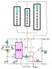
Hi guys, I started my first project and I need a little help. For the time being, I'm just trying to get the design down pat and not worried about exact values of components... yet. What I'm building can be easily depicted by the diagram in the first image "Circuit 1".
Essentially... we have a power source, a dimmer and then the modules. The requirements of the whole thing are:
1.) Each module may contain a different number of lights (I haven't yet figured out the upper and lower bounds on eactly how many LED's I will be having in each module i.e. I don't know whether the module with the smallest quantity of lights will have just 2 for example and the largest 300, however the range I think will be something in the order of 20-50.
2.) Despite the difference in the numbers of lights in each module, the single dimmer must be able to control all the modules in a way whereby each module has the exact same brightness regardless of the number of lights present. (NOTE: the lighting difference doesn't have to PERFECTLY the same but it should be close enough for the naked eye to not be able to tell the difference or MUCH of a difference).
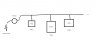
From some limited background reading and my basic understanding of electronics... I've decided that the 555 timer circuit is what I need... depicted in diagram 2 (Circuit 2) and taken from:
LED Dimmer Circuit - Lighting
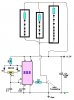
In the third image, is how I see it working in the final state... i.e. each of the modules is a SERIES of LED lights with an appropriately large and thereby different resistor for each series.
Questions:
1.) If I were to connect say 10 of these modules, what would be the best way of plugging in 10 wires into the two terminals on the main control panel? If you wrap them around a screw or something of the sort it would be messy and wouldn't be easy to disconnect individual modules or would be fiddly and a bit annoying trying to separate the wires.
2.) Will what I proposed fulfill point 2.) of my requirements? i.e. resistors like any components can be made to varying performances, so I'm not sure whether my simple adaptation/modification of the standard circuit will do the trick.
Finally:
From what I've said, is what I'm proposing going to work?
Essentially... we have a power source, a dimmer and then the modules. The requirements of the whole thing are:
1.) Each module may contain a different number of lights (I haven't yet figured out the upper and lower bounds on eactly how many LED's I will be having in each module i.e. I don't know whether the module with the smallest quantity of lights will have just 2 for example and the largest 300, however the range I think will be something in the order of 20-50.
2.) Despite the difference in the numbers of lights in each module, the single dimmer must be able to control all the modules in a way whereby each module has the exact same brightness regardless of the number of lights present. (NOTE: the lighting difference doesn't have to PERFECTLY the same but it should be close enough for the naked eye to not be able to tell the difference or MUCH of a difference).
From some limited background reading and my basic understanding of electronics... I've decided that the 555 timer circuit is what I need... depicted in diagram 2 (Circuit 2) and taken from:
LED Dimmer Circuit - Lighting
In the third image, is how I see it working in the final state... i.e. each of the modules is a SERIES of LED lights with an appropriately large and thereby different resistor for each series.
Questions:
1.) If I were to connect say 10 of these modules, what would be the best way of plugging in 10 wires into the two terminals on the main control panel? If you wrap them around a screw or something of the sort it would be messy and wouldn't be easy to disconnect individual modules or would be fiddly and a bit annoying trying to separate the wires.
2.) Will what I proposed fulfill point 2.) of my requirements? i.e. resistors like any components can be made to varying performances, so I'm not sure whether my simple adaptation/modification of the standard circuit will do the trick.
Finally:
From what I've said, is what I'm proposing going to work?
Attachments

Last edited: