windozeuser
Member
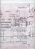
I'm trying to modify this robot controller (which operates on 120VAC) to operate on 12VDC. I have the wiring diagram, but it's confusing me. I found the connectors that I need to tap into "See below with the outlined pencil square". They are two 11 pin molex connectors. While on the diagram it only shows one with 10, in the real thing theres 11 o.o. Anyway, I need to find where to connect the 12VDC, 5VDC, and Ground voltages to each pin.
The power supply output 11 pin molex is connected to the power supply board; where 120VAC is converted to the rectified, regulated, and required voltages. This is where I need to tap into to feed it directly with the voltages with a car battery. For the 5 volt source, I'm just gonna use a voltage regulator.
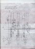
I'm having trouble reading this schematic. Plus I took some voltage measurements on the power supply output molex, and they are strange.
This is what I got:
Pin1 = -12v
Pin2 = NONE
Pin3 = +12v
Pin4 = NONE
Pin5 = NONE
Pin6 = NONE (not connected to anything but still read 9 volts)
Pin7 = Ground ?!?
Pin8 = +5v
Pin9 = NONE
Pin10 = NONE
Pin 11 = NONE
I connected it up and it's not powering it up. Can someone help me get these voltages right on the pins?
Thanks
The power supply output 11 pin molex is connected to the power supply board; where 120VAC is converted to the rectified, regulated, and required voltages. This is where I need to tap into to feed it directly with the voltages with a car battery. For the 5 volt source, I'm just gonna use a voltage regulator.
I'm having trouble reading this schematic. Plus I took some voltage measurements on the power supply output molex, and they are strange.
This is what I got:
Pin1 = -12v
Pin2 = NONE
Pin3 = +12v
Pin4 = NONE
Pin5 = NONE
Pin6 = NONE (not connected to anything but still read 9 volts)
Pin7 = Ground ?!?
Pin8 = +5v
Pin9 = NONE
Pin10 = NONE
Pin 11 = NONE
I connected it up and it's not powering it up. Can someone help me get these voltages right on the pins?
Thanks