Continue to Site

Welcome to our site!

Electro Tech is an online community (with over 170,000 members) who enjoy talking about and building electronic circuits, projects and gadgets. To participate you need to register. Registration is free. Click here to register now.

  • Welcome to our site! Electro Tech is an online community (with over 170,000 members) who enjoy talking about and building electronic circuits, projects and gadgets. To participate you need to register. Registration is free. Click here to register now.

Modify transmitter

Status
Not open for further replies.

jonrcflier

New Member
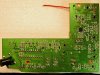
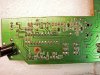
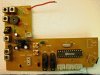
I have aquired a 3 channel RTF (Red Hawk) airplane which has a V-tail, and therefore, built in mixing of rudder and elevator functions. I would like to undo the mixing and use the transmitter for standard three channel operation. The control stick and throttle pots are connected to an EM78P459OTP ROM 24 pin IC. I really don't understand the circutry, but over the years I have built many electronic devices ranging from my first RC TX/Rcv'r to TV sets, so I am quite comfortable with making any changes needed.
Could anyone out there enlighten me and show me how to disable the mixing function ?
I just discovered this forum . . . . looks really good !
 
There should be a mix enable/disable somewhere on the controller itself, or inside. What brand/model is the transmitter?
 
The transmitteris a FlyZone 3-channel. It does have two switches in the front of the case with a label which says "switches must be in down position". I have tried the system with both switches up, one up & one down and vece-versa. Servo movemeny remains coupled. There are no additional switchen on the PWB. But, there are two jumper wires near one corner of the board next to a symbol that looks like a wide letter "V" over an inverted "T". The word "way5" is imprinted between the two sumbols. I will take a photo of the board for you later today.
 
Try to get a really good one of the whole board layout as clear as you can. Do you have a scope?
 
Sorry for the long delay. This is the board component side A and side B, plus a close-up of the PW side. The pitch, yaw and throttle connections are located to the lower left area of the board. The two servo reversing switches are near the center.
I should think the servo coupling is associated with the switches and/or the joystick input circutry.
In any case, I really appreciate your interest. I am anxious to learn about what you find.
 

Attachments

  • DSCN0271_edited.JPG
    DSCN0271_edited.JPG
    629.5 KB · Views: 153
  • DSCN0275_edited.JPG
    DSCN0275_edited.JPG
    573.8 KB · Views: 149
  • DSCN0273_edited.JPG
    DSCN0273_edited.JPG
    684 KB · Views: 160
Looks pretty simple. That large IC however is a micro controller so the mixing must be done on it. It's a ROM based controller so you won't be able to reprogram it. Don't have enough time to look at the circuit real closely right now and it's going to up to the program on the micro controller as to if it actually has a mix disable, but it may. If it has no mix disable then your only option would be to desolder the micro controller and put a socket on there to put your own micro controller but that's not exactly a light job and it'd probably be easier to buy a transmitter that. Depends on how much effort you really want to put into it.
 
I don't have a problem with removing the IC. Of course you are correct in that it would be easier to buy another transmitter, however, I would be interested in modifying this unit just for the fun of it and perhaps I could learn a bit more about micro controllers in the process. Or I could simply build a V-tail airplane . . . . but that's too logical.
Incidentally, I do have access to a scope along with a VOM and other assorted test instruments. Thanks again.
 
If none of the switches have any effect I would try snipping the wire link on Way5 as this is just tied low with a pullup to one of the microcontroller pins. This indicates that this is normally a switchable option and if it doesn't work then resoldering it is pretty easy.

Mike.
 
I initially thought perhaps that would be worth a try, but decided to wait for a response from someone who knows much more than I. As you say, restoring the jumper is quite simple . . . . so I'll give it a go. Thanks for you input!
 
The latest word on the E-Flight transmitter. I removed the jumper on Way5 and voila!, the coupling was removed. Everything looked good. Then I connected the motor to the receiver/ESC,, throttled up and the rcv'r was instantly fried !! Two small ICs, which appear to be SO-8 packages actually burst into flame. After this bit of excitement, I removed the motor and tried the rc'vr and guess what? It still worked (sort of) but the servos were coupled as before. Thus ends this episode.
 
The receiver was fried? That seems extremely weird. It just suddenly dawned on me though, the TX might not have been doing the mixing, the RX may have? Bursting into flames seems more than a little dramatic. If the jumper you cliped on the TX had something to do with the way it times things you may have over driven the servos which can seriously over current the RX which might explain something like that. Flames are really a bad sign though =O How about some pics of the RX? Also you never answered if you had a scope, if you have a scope, or even a PC sound card and are willing to use that you can scope the pins on the RX and TX and figure out what's going on.
 
Extremely wierd was my reaction as well. I'd say "flames are a bad sign" is an understatement! I'll take some photos of the remains. There are no identifiers visible on the two IC that flamed, and I removed most of the solder from the area in an attempt to trace connections . . . I don't know if that was a help or a hinderance. I'm guessing the chips were possibly dual MOSFET, but I can't really tell. I will replace the WAY5 jumper and try to determine if the receiver section actually still works.
I do have an old recurring sweep scope. as well as access to a very nice HP digital, but I am curious to know how a sound card can be used for signal tracing.
 
A sound card is nothing more than a DSO and a signal generator rated for streaming input/output with a bandwidth of 22khz. Modern sound cards have at least 2 stereo inputs (CD and line in) sometimes a stereo mic in, and many have more than one extra line in for additional CD or AUX-IN. The crosstalk is pretty bad, but can be adjusted for.

Although you can sample up to 96khz on most modern sound cards there are filter stages that limit the actual bandwidth to 0-20khz or so the falloff is rapid, the extra sampling rate over the available bandwidth for a sound card is to smooth out harmonic distortion (particularly in reproduction not sampling) Although for really pure audio samples a higher sampling rate for recording can pick up harmonics that might otherwise be missed.

The main disadvantage of a sound card is it is strictly AC coupled, although you may be able to make a chopper circuit to provide a DC bias, but that requires special hardware on the sending/receiving end and special hardware on the receiving/sending end. Also the voltage range is limited to LINE-IN input ranges (about 2 volts max) So you have to protect it with external hardware, or just never over drive it.
 
PS after your last post it doesn't sound too unusual. It very much sounds like you sent the receiver a massively out of spec but still readable PPM signal and the FETS fried from the higher switching rate as they were operating in their linear range. If you had a good eye and a steady hand for those few seconds where it worked fine you probably had the smoothest servo's you'll ever see =>
 
You're right . . . . they were smooth . . . . for about 30 seconds. It was an interesting experiment, but I will replace the jumper wire, order a new receiver and build a v-tail bird to use it in. Thanks for your interest and input!
 
Status
Not open for further replies.

New Articles From Microcontroller Tips

Back
Top