Continue to Site

Welcome to our site!

Electro Tech is an online community (with over 170,000 members) who enjoy talking about and building electronic circuits, projects and gadgets. To participate you need to register. Registration is free. Click here to register now.

  • Welcome to our site! Electro Tech is an online community (with over 170,000 members) who enjoy talking about and building electronic circuits, projects and gadgets. To participate you need to register. Registration is free. Click here to register now.

modify hall sensor and coil on plug pack

Status
Not open for further replies.

DustyB

New Member
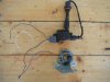
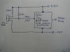
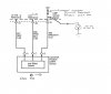
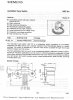
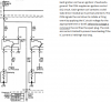
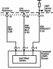
This is my first post. I have an old 1937 hit-n-mis stationary engine that is missing its complete ignition system. In an attempt to build my own system I salvaged a coil pack and hall sensor from a 2002 GMC Truck Envoy L6-4.2L. I plan to place the hall sensor near a pin on the cam shaft that used to operate the points. I know very little about electronics however and need some help. I'm including two pictures of what I found in AllData for these components. My question is can I connect the hall signal directly to the coil's switch transistor? I wont be using any part of the Envoy's PCM. I haven't tried it yet because I'm afraid I'll smoke the hall sensor and a replacement is more than $50. Another question, how do I deal with the engine stopped such that the hall sensor is closed? I don't want to discharge the battery or fry the coil as a result. Perhaps some kind of circuit could break the connection if it was left for more than 1/2 second.

Thank you for your assistance,
 

Attachments

  • coil.PNG
    coil.PNG
    103.6 KB · Views: 925
  • sensor.PNG
    sensor.PNG
    54 KB · Views: 986
Last edited:
Hi Dusty. Here is a pict of a COP & hall device i wired up to see if it works & it does. You should have no troubles with the coil you have selected, as it is current limited if turned on too long. Your Hall device will need a pull up resistor of 2.2K ohm betwean A & B on your Hall sensor. Ground C, feed 12V to A. B will feed the Ign coil control terminal. Usualy to turn a Hall on/off you need a soft iron blade to go betwean the sensor & the magnet.
 

Attachments

  • IGNITER.1.JPG
    IGNITER.1.JPG
    3 MB · Views: 907
  • IGNITER.2.JPG
    IGNITER.2.JPG
    2.5 MB · Views: 1,303
Hey, thank you for taking a look at my question. This is wonderful news.

Since my hall sensor already has a magnet inside it I probably won't need a magnet on the cam. It seems to have quite a powerful magnet in there. As far as being "current limited" I didn't know if that was built into the COP or something provided by the vehicle PCM.

Earlier ignition coils, before these HEI and CD ignitions, needed "dwell" which I assume is the fully charge the coil's magnetic field. I expect I'll find enough dwell with my cam's pin near the sensor especially since top speed is only 500 rpm and the cam on this engine only turns 1/4 that or 125 rpm. Its the first engine I've ever seen that used 1/4 ratio which they did since the original water pump was driven off the cam.

Again, thank you.
 
Going by the circuit description of the COP, the the current limiting is built into the COP. Dwell is not a problem with this system.
 
Your sketch shows a 100 ohm resistor, what does that do? Sorry I don't konw too much about electronics.
 
The 100 ohm resistor is just for current limiting, just incase the hall device develops a fault. Never be sorry for asking a question, Im 64 yrs & still ask questions ( i gues the day you stop asking questions is your dead)
 
Is the signal from a basic Hall sensor pretty much a square wave? A mechanic friend told me that some automotive hall sensors encapsulate a Schmidt trigger inside the device which I'm sure would square it up. Not knowing if mine has such an internal circuit should the coil triggering still be reliable?

I'm not sure my terminology is correct, I think of high signal as being more nearly +12v in my case, when the Hall switch is open the signal is low? How do you know when the COP transistor switches, is it the arrow in the transistor's diagram which indicates which signal, high or low, that switches the transistor? I ask these questions because I'm a computer programmer, auto mechanic and handyman. Electronics has always fascinated me but I have no training in it. I certainly wouldn't mind another lifetime to try electrical and electronics.

Thanks,
 
The COP usualy like a clean square wave to turn it on/off. Have included your circuit with alterations to check what it does, prefer to use an analouge meter to show that it switches on/off. Have included a hall sensor HKZ101 which is an ignition triger using a soft iron blade to activate it. This is what i was using, they are avalable here localy for $20 from Jaycar ZD1900. The COP i was using turns on with a + rise signal & off on -- fall of signal.
 

Attachments

  • Hall sensor.1.jpg
    Hall sensor.1.jpg
    178.7 KB · Views: 974
  • HKZ101 hall.1.jpg
    HKZ101 hall.1.jpg
    991.8 KB · Views: 816
  • HKZ101 hall.2.jpg
    HKZ101 hall.2.jpg
    608.1 KB · Views: 695
  • HKZ101 hall.3.jpg
    HKZ101 hall.3.jpg
    1,016 KB · Views: 703
This is how the circuit should look. Also the square wave should be about 50% duty cycle (it is in most Hall activated Ign systems ive seen.) Also when experimenting make sure you have a spark plug conected to the coil & the ground is tied to the spark plug base. Other wise you may damage the COP due to internal arcing.
 

Attachments

  • COP & HALL switch.jpg
    COP & HALL switch.jpg
    447.5 KB · Views: 664
The circuit is working fine for me, again thank you for your assistance. I have three further questions about this circuit.
1. The COP has cooling fins which warm up significantly. I can't say they are hot to the touch after triggering it <50 times, but it surprises me how warm it does get. Should I expect it to get hot?
2. If I wanted to add an LED to indicate when the hall sensor is conducting, would I place it between terminal B & C on the hall sensor? Do I need a current limiting resistor for the LED?
3. My hall sensor has an internal bias magnet so it senses non magnetized iron nearby but its range is very short. Are there hall sensors available that would have longer range and drop right into this circuit (operate on 12v)? I'm a little concerned about mounting my sensor on a bracket with the vibration from my engine. To get it close enough I'm afraid of a collision.
 

Attachments

  • COP Ignition.png
    COP Ignition.png
    21.1 KB · Views: 620
Last edited:
Hi Dusty, 1. It will get fairly warm. 2. A LED may be too mutch current draw for the Hall device. 3. It is a 12V device you are using & Hall devices are not that sensitive over larger distances. Just make the mount fairly strong.
 
Status
Not open for further replies.

Latest threads

New Articles From Microcontroller Tips

Back
Top