Continue to Site

Welcome to our site!

Electro Tech is an online community (with over 170,000 members) who enjoy talking about and building electronic circuits, projects and gadgets. To participate you need to register. Registration is free. Click here to register now.

  • Welcome to our site! Electro Tech is an online community (with over 170,000 members) who enjoy talking about and building electronic circuits, projects and gadgets. To participate you need to register. Registration is free. Click here to register now.

Mobile Phone detector for GSM, 3G and 4G devices

Status
Not open for further replies.

Lakshikun

New Member
Hello! I'm doing this side project for a mobile phone detector. I went through much documentation, and I was able to use this circuit diagram to produce the following assemble.

1636732770029.png


The following photos and video show my nth attempt at making the circuit work.

1636732847888.png


https://streamable.com/tt3eeh

My results:

1. I have very limited range. At max, 1.4 m
2. I get GSM readings fine, but I'm unable to have consistent results from 3G and 4G devices.

I would love to have this circuit operational. Your help is very much appreciated.
 
Unfortunately that is a typical "internet schematic" by someone who does not understand electronics.
It's sad that there are lots of examples that just do not work as claimed and can totally mislead beginners.


The CA3130 opamp is not suitable for radio frequencies and its gain drops to zero at a few MHz - while mobile phones operate at 800-900 MHz and higher frequency bands.

The only reason it does anything is when the RF signal is strong enough some semiconductor junctions start directly rectifying it and upsetting the bias...

Also note that for anything to work properly at the frequencies involved, all construction is extremely critical and breadboard circuits will not work at all, or at least not as expected; connection lengths are critical, as are stray capacitance and inductance. Each piece of wire or connection has delay and resonance effects at 900MHz like a piece a hundred times longer at "shortwave" type frequencies, or a million times longer than at audio frequencies.


For info:
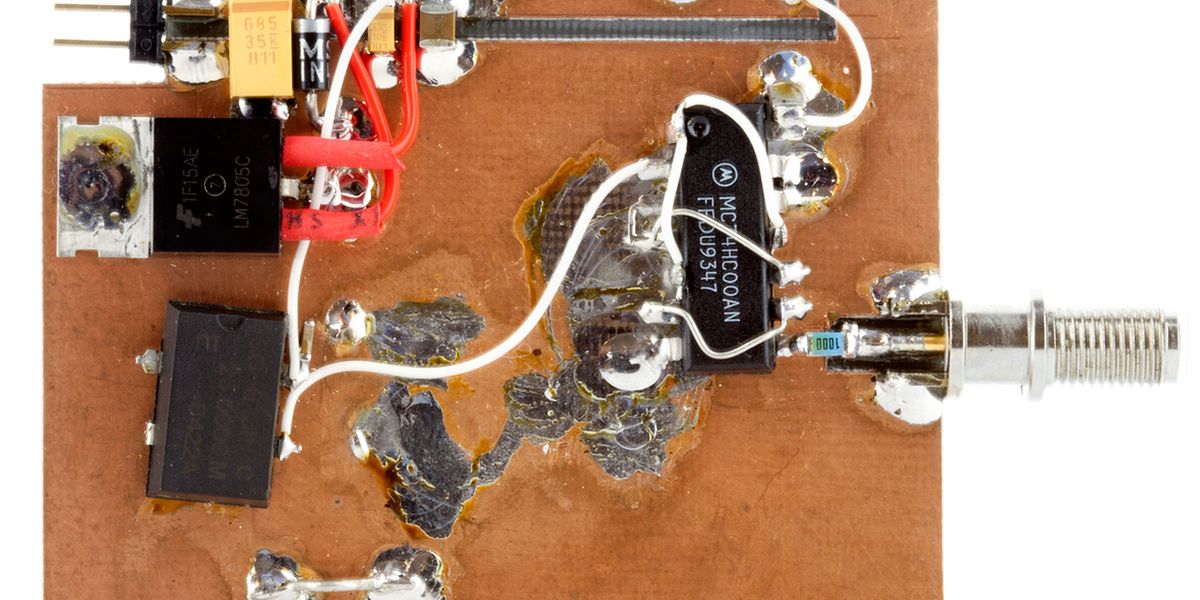
Prototyping for UHF frequencies needs to be done on ground-plane boards, either etched / milled "stripline" tracks or "Manhattan" or "dead bug" style, as the examples below.

Stripline examples:

Manhattan style - small pads of PCB on top of a copper ground plane board.

1636742459651.jpeg


And an article on "dead bug" style:
 
Last edited:
Status
Not open for further replies.

Latest threads

New Articles From Microcontroller Tips

Back
Top