corvese210
New Member
Hello,
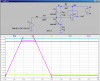
I have a voltage source that will be outputting voltages between -20V and +20V. I need a circuit that will regulate this voltage between +0.5V and around +14V. Anything below 0.5 must stay at 0.5 while anything higher than 14 must be kept at 14...all voltages between must be their actual values.
I know I can use a zener diode regulator circuit to keep it below 14V but I am not sure what to do with the minimum voltage value, espically once it goes negative. Any negative value must be held at 0.5V.
Any suggestions????
Thanks for your help!
")