Electro Tech is an online community (with over 170,000 members) who enjoy talking about and building electronic circuits, projects and gadgets. To participate you need to register. Registration is free. Click here to register now.
Welcome to our site! Electro Tech is an online community (with over 170,000 members) who enjoy talking about and building electronic circuits, projects and gadgets. To participate you need to register. Registration is free. Click here to register now.
What is the best choice to amplify the output signal of an electert or dynamic mike?
I my self designed the below circuit. Is it just right to do so? Is there any trim needed for the said circuit?
Your input impedance is only 10k ohms which will load down and reduce the output from an electret mic. If the first opamp is non-inverting then it can have a higher input impedance of 100k ohms (and the input capacitor can be smaller).
Your gain is only 27/10 x 27/10= 7.29 but since it loads down the mic then the actual gain is less. It should be 50 to 200 from a single audio opamp like a TL071.
The opamp does not need a dual-polarity supply if it is biased correctly.
The FET in a two-wires electret mic is a follower with no voltage gain. It self-biases its input but it must be powered.
The new schematic in post #5 has a max gain of 650 which is too high. It does not need 2 opamps, a single audio opamp can have an adjustable gain from 50 to 200.
It has too much DC gain which could cause an error of over 3VDC at its output.
So we should say that we need to provide supply voltage, not bias voltage. After all, we don't speak of "bias voltage" to an op-amp, even though some of Vcc may go towards biasing the amp.
The FET in a two-wires electret mic is a follower with no voltage gain. It self-biases its input but it must be powered.
The new schematic in post #5 has a max gain of 650 which is too high. It does not need 2 opamps, a single audio opamp can have an adjustable gain from 50 to 200.
It has too much DC gain which could cause an error of over 3VDC at its output.
Actually I use 2 op-amps to be in the safe side regarding the GBP of the TL074. As you can see the second op-amp has a feedback POT which can change the overall gain. Actually I am interested in to have a high gain amplifier so that pick even small voices if needed.
are you satisfied by the input high pass filter of my last pic? I calculated the said filter so that I get a corner frequency as low as of say 1/5 of the lower audible sound (1/5 of 20Hz I mean).
By the way dont you think that I need to use a cap between 2 stages?
Why and how it has DC gain? How to lower/ remove the dc gain yet get the desired AC gain?
A TL074 is too noisy (hiss) for the extremely high gain you want. An OPA2134 (dual) or OPA4134 (quad) are much quieter.
Your highpass filter cuts off at 4Hz so it passes voices down to about 40Hz and passes air conditioning noises and jet airplane noises down to 4Hz. Cutoff the mic at 40Hz.
Capacitors pass AC but block DC so you should use them. Your feedback capacitors have very low values which causes the capacitors to have very high values.
I thought that TL07X is a LOW noise op-amp...
Unfortunately I have no access to the OPA chip. Can I add another stage op-amp to lower the HIS you are talking about? Or any other methoid/other op-amp chip to reduce it?
2 quaetions regarding your modification in above circuit:
Dont you think that the DC gain of U4: C would be zero not 1 by adding the coupling cap at its input?
You added another cap between the R3 and ground too, to lower the DC gain, But the circuit originally has an input cap (C26), So I guess there would not be any dc signal at the input of the fist chip, so Why we should add the 10uF cap between the R3 and ground to lower the DC gain while it seems that there is not such a DC value at the input of the chip?
By the way Is not the 10uF cap too much to be used?
No. But if you chop off all high audio frequencies like an AM radio then the hiss will be reduced. But then rumble sounds from cheap opamps will be heard so you can chop off all low audio frequencies like a telephone.
2 questions regarding your modification in above circuit:
Dont you think that the DC gain of U4: C would be zero not 1 by adding the coupling cap at its input?
No, the DC gain is 1 (it is a DC follower with no gain and no loss). A gain of 0 is no signal.
Why we should add the 10uF cap between the R3 and ground to lower the DC gain while it seems that there is not such a DC value at the input of the chip?
It is a simple calculation. 10uf into 1k ohms cuts frequencies below 16Hz. Since there are two RC networks then the total cuts frequencies below 32Hz.
Your 330nF input capacitor has its value much too big to feed the 120k input resistor because it cuts frequencies below only 4Hz. It can be 100nF instead then it will cut frequencies below 13.2Hz.
What is the problem if the capacitor happens to be 330nF? I have at least 3 other high pass Rc in the circuit (not shown) which cause the cutoff frequency happens to be at least 30Hz or more...
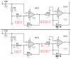
Without an input coupling capacitor it amplifies DC so its DC gain is 25 as shown in the upper schematic.
With the input coupling capacitor that blocks DC then its DC gain is only 1 as shown in the lower schematic.
Without an input coupling capacitor it amplifies DC so its DC gain is 25 as shown in the upper schematic. With the input coupling capacitor that blocks DC then its DC gain is only 1 as shown in the lower schematic.
Because the capacitor blocks any input DC voltage changes and the opamp becomes a "follower" of the DC voltage on its (+) input.
If the voltage on the (+) input changes 1V then the output of the opamp also changes 1V. So the DC gain is 1.
Because the capacitor blocks any input DC voltage changes and the opamp becomes a "follower" of the DC voltage on its (+) input.
If the voltage on the (+) input changes 1V then the output of the opamp also changes 1V. So the DC gain is 1.
Second, what do you mean by Follower really? Are you refering to op-amp buffers? if so, the input in a buffer is the "+" pin, while here in "U4: C" (the below left in your post # 11) the input is the "-" pin...
The DC output of the opamp is connected to its (-) input then the DC gain is 1 and the output DC voltage will be the same as its input (+) voltage.
Second, what do you mean by Follower really? Are you refering to op-amp buffers? if so, the input in a buffer is the "+" pin, while here in "U4: C" (the below left in your post # 11) the input is the "-" pin...
The (+) DC input connects to ground and the (-) DC input connects to its output, not to the input. The input is AC because its DC is blocked by the input coupling capacitor.
A follower is a buffer with a gain of 1.
This site uses cookies to help personalise content, tailor your experience and to keep you logged in if you register.
By continuing to use this site, you are consenting to our use of cookies.