hi
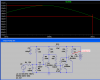
i have this circuit that i found on the internet
**broken link removed**
this is where i found it
**broken link removed**
i want to know a few things
1. what voltage would you expect to get from this circuit at the end
2. the transistors are npn does that mean i can use any npn transistor or do i have to use a persific one
3. if i attach the positive of this circuit to a lm3916 with a Vref of 1.25 will all the lights light up properly or do i need to do something else
4. the capacitors used in this all of them have one straignt line and one curved line does that mean that they are electrlitic capacitors because they do not have the plus sign next to them
5.the capacitor in the top left does not have a what value is it or doesnt it matter
6. what would the supply voltage be and where will it be placed after reading the persons website am i right in saying that the TRS connect is where the supply goes in
if so where does the signal come out
sorry if this is long