Continue to Site

Welcome to our site!

Electro Tech is an online community (with over 170,000 members) who enjoy talking about and building electronic circuits, projects and gadgets. To participate you need to register. Registration is free. Click here to register now.

  • Welcome to our site! Electro Tech is an online community (with over 170,000 members) who enjoy talking about and building electronic circuits, projects and gadgets. To participate you need to register. Registration is free. Click here to register now.

micromouse sensor

Status
Not open for further replies.

banh

New Member
I'm design micromouse sensors (topdown), as the maze is in black lines on white background (not walls).
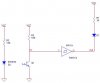
Currently my circuit is very simple.
However, as my friend suggests I should filter out ambient light, and have no clue about it.

How should I do that filtering?
 

Attachments

  • simple-sensor.jpg
    simple-sensor.jpg
    12.3 KB · Views: 1,389
spindrah said:
turn off infrered led

take your reading

turn on infrered

take reading2

reading2 - reading = no ambient

Unfortunately that wouldn't work, the circuit only provides a high or low logic output.

You could try fitting an IR filter over the phototransistor, this will reduce visible light interference. But the best way is to modulate the IR LED, and detect the modulation after the phototransistor - which is how remote controls work, to avoid interference from ambient light.
 
ok i didn't realy look at it

i was thinking of reading the photo trans with an A2D pin from the pic

if you are useing a pic that is an easy way to do it

thats what i use on my balanceing bot, to get the distance from the floor
but its also vary sensitive to color change
 
some suggest pulsing the infrared transmitter ( to save the power instead of always transmitting). Every time we enable the transmitter, wait for a while and read in from the receiver side. At the receiver put a high pass filter to filter out ambient light. I'm not sure how this works, and how to implement it.. Is it that for high pass filter just put a RC circuit ?
 
some suggest pulsing the infrared transmitter ( to save the power instead of always transmitting).

No, pulsing transmitter is not only to save pwr. It's to make a frequency filter. If you transmit all the time, and outdoor, you may get noises from sunlight, or other IR sources, heats... You transmit at high frequency, you will recieve the right signal. They used to use about 40KHz for IR tx and rx.
 
My connection is the same as above, but at the transmitter side, instead of connecting to GND, i connect to clock.
At the other side, I measure voltage before going through filter.
However as clock frequency increases, p-p voltage measured decreases, and only reach max 5V when about 1Khz clock. Waveform at receiver also is not square.
Any thing wrong with my circuit?
 
Status
Not open for further replies.

Latest threads

New Articles From Microcontroller Tips

Back
Top