Hello, my name is Enrique and I am developing a micromotor controller design (manufacturated by Faulhaber, series 0308...B, Brushless and Sensorless).
In fact, we have a severe problem trying to watch the Back-emf for calculating the zero crossing to control perfectly the motor rotation.
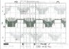
Using the controller proportionate by the manufacturer, we can see in the oscilloscope:
- FAULHABER CONTROLLER.BMP
And detailed steps:
- DETAILED_FAULHABER.JPG
As you can see, it is clear the progresive inductance discharge, so it is quite easy to calculate the zero crossing.
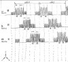
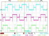
In our case we have this signal, (test without PWM to simplify the signal and visualize the back emf):
- OUR SIGNAL_NO_PWM.BMP
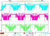
And test with PWM (freehand drawing signal, standby signal in low level instead of high level, but getting the same results doing a 180 degrees turn):
- OUR SIGNAL_PWM.JPG
As you can see, we cannot visualize that inductance current discharge, otherwise we can see a step signal, making complicated the zero crossing computation:
The characteristics for the used micromotor:
- Brushless DC-Micromotor.PDF
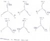
We do the following steps in the microcontroller firmware:
- DETAILED_STEPS.JPG
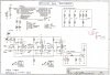
- SCHEMA.JPG
(when a terminal is left open to watch the back-emf, we pull to ground the base/gate of transistors).
For summarising, we want to know what it is happening to us and if we are doing something wrong to see the back-emf (in electronics or in firmware).
We hope your answers and thank you for any idea.
Regards,
Enrique
In fact, we have a severe problem trying to watch the Back-emf for calculating the zero crossing to control perfectly the motor rotation.
Using the controller proportionate by the manufacturer, we can see in the oscilloscope:
- FAULHABER CONTROLLER.BMP
And detailed steps:
- DETAILED_FAULHABER.JPG
As you can see, it is clear the progresive inductance discharge, so it is quite easy to calculate the zero crossing.
In our case we have this signal, (test without PWM to simplify the signal and visualize the back emf):
- OUR SIGNAL_NO_PWM.BMP
And test with PWM (freehand drawing signal, standby signal in low level instead of high level, but getting the same results doing a 180 degrees turn):
- OUR SIGNAL_PWM.JPG
As you can see, we cannot visualize that inductance current discharge, otherwise we can see a step signal, making complicated the zero crossing computation:
The characteristics for the used micromotor:
- Brushless DC-Micromotor.PDF
We do the following steps in the microcontroller firmware:
- DETAILED_STEPS.JPG
- SCHEMA.JPG
(when a terminal is left open to watch the back-emf, we pull to ground the base/gate of transistors).
For summarising, we want to know what it is happening to us and if we are doing something wrong to see the back-emf (in electronics or in firmware).
We hope your answers and thank you for any idea.
Regards,
Enrique