Continue to Site

Welcome to our site!

Electro Tech is an online community (with over 170,000 members) who enjoy talking about and building electronic circuits, projects and gadgets. To participate you need to register. Registration is free. Click here to register now.

  • Welcome to our site! Electro Tech is an online community (with over 170,000 members) who enjoy talking about and building electronic circuits, projects and gadgets. To participate you need to register. Registration is free. Click here to register now.

microcontroller

Status
Not open for further replies.

prachi

New Member
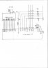
i am having mp project of position control of stepper motor
motor used is M42SP-5(12 V 269mA 345pps),
DRIVER USED IS ULN2803
i will be inputing no of steps n half steps through matrix key board n using lcd display to show the angle(my plan!)
now i am having problem with writing code i am using 89c51 to control.
How to calculate delay to be given to motor, how it should be given and if i want to do half steppin how to do it.(i just have general idea about in which sequence phases of motor should be activated)
Also tell me how the code should be written and before putting in 4 application how i can check if i dont have any logical problem with code?
please help me :p
prachi
 
hello sarang, :)

thank u for the help u provided.
i still have few doubts
1. if i am using 15v,1A Xmer folloed by 7805 and 7812 regulator ic do i need to connect current booster transister?(from same Xmer i am giving secondary to bith ic's)
2.i am sending the program . I am expecting this program rufly to first ask for password then take no of step from user then move by that angle and then if user wants to go back then go back to original position . assembler i am using is mide-51
it will be great if can go through the program and tell me if there are any problems as soon as possible as u have the prctical experience what works better.
3. if u know what are denger signs that we students are most likely to make mistakes then let us know.
thank you
prachi


DB0 EQU P1.0
DB1 EQU P1.1
DB2 EQU P1.2
DB3 EQU P1.3
DB4 EQU P1.4
DB5 EQU P1.5
DB6 EQU P1.6
DB7 EQU P1.7
EN EQU P3.7
RS EQU P3.6
RW EQU P3.5
DAT EQU P1


n1 EQU 04h
n2 EQU 04h
n3 EQU 04h
n4 EQU 04h

DIRN EQU 00H
FULL EQU R2
STEPS EQU R3
HALF EQU 01H
ROW0 EQU P2.4
ROW1 EQU P2.5
ROW2 EQU P2.6


start code 0000h
org start

LCALL INIT_LCD
PASS: LCALL CLEAR_LCD
MOV A,#'E' ;Display "Enter Password"
LCALL WRITE_TEXT
MOV A,#'n'
LCALL WRITE_TEXT
MOV A,#'t'
LCALL WRITE_TEXT
MOV A,#'e'
LCALL WRITE_TEXT
MOV A,#'r'
LCALL WRITE_TEXT
MOV A,#' '
LCALL WRITE_TEXT
MOV A,#'P'
LCALL WRITE_TEXT
MOV A,#'a'
LCALL WRITE_TEXT
MOV A,#'s'
LCALL WRITE_TEXT
MOV A,#'s'
LCALL WRITE_TEXT
MOV A,#'w'
LCALL WRITE_TEXT
MOV A,#'o'
LCALL WRITE_TEXT
MOV A,#'r'
LCALL WRITE_TEXT
MOV A,#'d'
LCALL WRITE_TEXT

LCALL READ ;Read 4-digit password and go ahead when password is correct
CJNE A,#n1,PASS
LCALL READ
CJNE A,#n2,PASS
LCALL READ
CJNE A,#n3,PASS
LCALL READ
CJNE A,#n4,PASS

LCALL CLEAR_LCD ;Display "Enter Direction"
MOV A,#'E'
LCALL WRITE_TEXT
MOV A,#'n'
LCALL WRITE_TEXT
MOV A,#'t'
LCALL WRITE_TEXT
MOV A,#'e'
LCALL WRITE_TEXT
MOV A,#'r'
LCALL WRITE_TEXT
MOV A,#' '
LCALL WRITE_TEXT
MOV A,#'D'
LCALL WRITE_TEXT
MOV A,#'i'
LCALL WRITE_TEXT
MOV A,#'r'
LCALL WRITE_TEXT
MOV A,#'e'
LCALL WRITE_TEXT
MOV A,#'c'
LCALL WRITE_TEXT
MOV A,#'t'
LCALL WRITE_TEXT
MOV A,#'i'
LCALL WRITE_TEXT
MOV A,#'o'
LCALL WRITE_TEXT
MOV A,#'n'
LCALL WRITE_TEXT ;0 FOR ANTI-CLOCKWISE,ANY OTHER KEY CLOCKWISE


LCALL READ
SETB DIRN
CJNE A,#00H,AHEADD
CLR DIRN
MOV B,A

AHEADD: ;Display direction L= left & R= Right
CLR RS ;Positioning Cursor
MOV DAT,#0C0H
SETB EN
CLR EN
LCALL WAIT_LCD

ORL A,#00H ;?? aSK KOMI
MOV A,#'R'
JNZ RIGHT
MOV A,#'L'
RIGHT:
LCALL WRITE_TEXT
LCALL CLEAR_LCD ;Display Full Rotation
MOV A,#'F'
LCALL WRITE_TEXT
MOV A,#'u'
LCALL WRITE_TEXT
MOV A,#'l'
LCALL WRITE_TEXT
MOV A,#'l'
LCALL WRITE_TEXT
MOV A,#' '
LCALL WRITE_TEXT
MOV A,#'R'
LCALL WRITE_TEXT
MOV A,#'o'
LCALL WRITE_TEXT
MOV A,#'t'
LCALL WRITE_TEXT
MOV A,#'a'
LCALL WRITE_TEXT
MOV A,#'t'
LCALL WRITE_TEXT
MOV A,#'i'
LCALL WRITE_TEXT
MOV A,#'o'
LCALL WRITE_TEXT
MOV A,#'n'

LCALL READ ;Read data - 1 digit,(0-9)
MOV FULL,A
ADD A,#30H
LCALL WRITE_TEXT

LCALL CLEAR_LCD ;Display No.of Steps
MOV A,#'N'
LCALL WRITE_TEXT
MOV A,#'o'
LCALL WRITE_TEXT
MOV A,#' '
LCALL WRITE_TEXT
MOV A,#'o'
LCALL WRITE_TEXT
MOV A,#'f'
LCALL WRITE_TEXT
MOV A,#' '
LCALL WRITE_TEXT
MOV A,#'S'
LCALL WRITE_TEXT
MOV A,#'t'
LCALL WRITE_TEXT
MOV A,#'e'
LCALL WRITE_TEXT
MOV A,#'p'
LCALL WRITE_TEXT
MOV A,#'s'
LCALL WRITE_TEXT

CLR RS
MOV DAT,#0C0H
SETB EN
CLR EN
LCALL WAIT_LCD

;Input no. of steps (0-99)
LCALL READ ;Input first digit
MOV B,A
ADD A,#30H
LCALL WRITE_TEXT
MOV A,B
SWAP A
MOV B,A

LCALL READ ;Input second digit
MOV R4,A ;Read digit in R4
ADD A,B
MOV R5,A
MOV A,R4
ADD A,#30H
LCALL WRITE_TEXT
MOV A,R5 ;Convert to HEX and store in steps
MOV B,#16H
DIV AB
SWAP A
ADD A,B
MOV STEPS,A ;?????

MOV A,#'.' ;Display '.'
LCALL WRITE_TEXT

LCALL READ ;Input whether half-step or no half step
ADD A,#30H
LCALL WRITE_TEXT
CLR C
SUBB A,#30H
SETB HALF
CJNE A,#00H,CALC_ANG
CLR HALF

CALC_ANG: MOV B,#46H ;B <-- 75 (Decimal)
MOV R6,#00H ;lower
MOV R7,#00H ;higher
CONVERT: MOV R0,#00H ;carry
MOV A,R6
ADD A,R5
JNC NOCARRY
MOV R0,#01H
NOCARRY: DA A;??????
JNC NOCANS
MOV R0,#01H
NOCANS: MOV R6,A
MOV A,R7
ADD A,R0
DA A
MOV R7,A
DJNZ B,CONVERT
;R7-R6 contains ans, now full no. is in R7-R6
MOV RS,#00H
JB HALF,AHEADN
MOV R5,#05H
MOV A,R6
ADD A,#37H
JNC CONTINUE
MOV R0,#01H
CONTINUE:
DA A
JNC CONT2
MOV R0,#01H
CONT2:
MOV R6,A
MOV A,R7
ADD A,R0
DA A
MOV R7,A
AHEADN: MOV A,R7
ANL A,#0F0H
SWAP A
ADD A,#30H
LCALL WRITE_TEXT

MOV A,R7
ANL A,#0F0H
ADD A,#30H
LCALL WRITE_TEXT

MOV A,R6
ANL A,#0F0H
SWAP A
ADD A,#30H
LCALL WRITE_TEXT

MOV A,#'.'
LCALL WRITE_TEXT

MOV A,R6
ANL A,#0FH
ADD A,#30H
LCALL WRITE_TEXT

MOV A,R5
ADD A,#30H
LCALL WRITE_TEXT

;Stepper motor business


LCALL CLEAR_LCD
MOV A,#'G'
LCALL WRITE_TEXT
MOV A,#'o'
LCALL WRITE_TEXT
MOV A,#' '
LCALL WRITE_TEXT
MOV A,#'B'
LCALL WRITE_TEXT
MOV A,#'a'
LCALL WRITE_TEXT
MOV A,#'c'
LCALL WRITE_TEXT
MOV A,#'k'
LCALL WRITE_TEXT
MOV A,#'?'
LCALL WRITE_TEXT

ORL A,#00H
MOV A,#'N'
JZ NO
MOV A,#'Y'
NO: LCALL WRITE_TEXT
here: sjmp here

;Stepper stuff
CALL MOTOR


INIT_LCD: ;Subroutine to initialize LCD
CLR RS
MOV DAT,#38h
SETB EN
CLR EN
LCALL WAIT_LCD
CLR RS
MOV DAT,#0Eh
SETB EN
CLR EN
LCALL WAIT_LCD
CLR RS
MOV DAT,#06h
SETB EN
CLR EN
LCALL WAIT_LCD
RET

WAIT_LCD:
CLR EN ;Start LCD command
CLR RS ;It's a command
SETB RW ;It's a read command
MOV DAT,#0FFh ;Set all pins to FF initially
SETB EN ;Clock out command to LCD
MOV A,DAT ;Read the return value
JB ACC.7,WAIT_LCD ;If bit 7 high, LCD still busy
CLR EN ;Finish the command
CLR RW ;Turn off RW for future commands
RET

CLEAR_LCD:
CLR RS
MOV DAT,#01h
SETB EN
CLR EN
LCALL WAIT_LCD
RET

WRITE_TEXT:
SETB RS
MOV DAT,A
SETB EN
CLR EN
LCALL WAIT_LCD
RET

READ: ;(0-3) OF PORT 2 IS INPUT AND (4-7) IS OUTPUT
MOV A,#0FH
MOV 0A0H,A
;Check if all keys are open
OPEN: CLR P2.4
CLR P2.5
CLR P2.6
MOV A,0A0H ;????
ANL A,#0FH
CJNE A,#0FH,OPEN ;If key key is not open, wait till open
CALL DBONCE ;Once all keys are open ,wait for sometime for bouncing to end
;Check for key closure (ROWS < 0FH)
;All columns are already low
SETB P2.7
ISPRESS:
MOV A,0A0H
ANL A,#0FH
CLR C
SUBB A,#0FH
JNC ISPRESS ;IF ROW=0FH,WAIT FOR KEY CLOSURE
;Now that a key has been pressed,identify the key
;Make one column low at a time
CLR P2.7 ;Make col 0 '0'
CLR P2.4
SETB P2.5
SETB P2.6
MOV A,0A0H
ANL A,#0FH
CLR C
SUBB A,#0FH
JZ COLONE
JB ROW0,FOUR
RET
FOUR: JB ROW1,SEVEN
MOV A,#04H
RET
SEVEN: MOV A,#07H
RET
;Make column1 '0'
COLONE: SETB P2.4
CLR P2.5
SETB P2.6
MOV A,0A0H
ANL A,#0FH
MOV 2FH,A
CLR C
SUBB A,#0FH
JZ COLTWO
JB ROW0,FIVE
MOV A,#02H
RET
FIVE: JB ROW1,EIGHT
MOV A,#05H
RET
EIGHT: JB ROW2,ZERO
MOV A,#08H
RET
ZERO: MOV A,#00H
RET
;Make column2 '0'
COLTWO:
SETB P2.4
SETB P2.5
CLR P2.6
MOV A,#0A0H
ANL A,#0FH
MOV 2FH,A
JB ROW0,SIX
MOV A,#03H
RET
SIX: JB ROW1,NINE
MOV A,#06H
RET
NINE: JB ROW2,POINT
MOV A,#09H
RET
POINT: MOV A,#0AH
RET
DBONCE:

CLR TR0
MOV TMOD,#01H
MOV TL0,#0F0H
MOV TH0,#0D8H
SETB TR0
SAME: JNB TF0,SAME
RET


;SUBROUTINE MOTOR
;``````````````````
MOTOR:

MSTART:
MOV R5,#88H

MOV B,R2
MOV A,B
JZ DOWN
MOV R4,B
UP:MOV B,#31H

LCALL STEP
DJNZ R4,UP

DOWN:
MOV B,R3
MOV A,B
JZ DOWN2
INC 0F0H
LCALL STEP

DOWN2:

JNB 01H,DOWN3

MOV A,80H
ANL A,#0FH

JB 00H,COUNTERCLOCK

CJNE A,#08H,NEXT1
MOV 80H,#0CH
LJMP TAIL

NEXT1: CJNE A,#04H,NEXT2
MOV 80H,#06H
LJMP TAIL

NEXT2: CJNE A,#02H,NEXT3
MOV 80H,#03H
LJMP TAIL

NEXT3:
MOV 80H,#09H
LJMP TAIL

COUNTERCLOCK:

CJNE A,#08H,NEXT5
MOV 80H,#09H
LJMP TAIL

NEXT5: CJNE A,#04H,NEXT6
MOV 80H,#0CH
LJMP TAIL

NEXT6: CJNE A,#02H,NEXT7
MOV 80H,#06H
LJMP TAIL

NEXT7:
MOV 80H,#03H
TAIL:
CALL DELAY

DOWN3:

JNB 02H,LAST
CPL 00H
LJMP MSTART

LAST:RET

;SUBROUTINE STEP
;``````````````````
STEP:
MOV R6,B
REPEAT: MOV A,R5
ANL A,#0FH
MOV 80H,A
CALL DELAY
JB 00H,ANTI
RR A
SJMP SKIP
ANTI: RL A
SKIP: DJNZ R6,REPEAT
RET

;SUBROUTINE DELAY
;````````````````````
DELAY:
CLR TR0
MOV TMOD,#01H
MOV TL0,#60H
MOV TH0,#0F0H
SETB TR0
HERE2: JNB TF0,HERE2
RET

END :D :D :)
 
prachi said:
1. if i am using 15v,1A Xmer folloed by 7805 and 7812 regulator ic do i need to connect current booster transister?(from same Xmer i am giving secondary to bith ic's)
This means 15V and 1A is the max rating of the whole transformer and you can work in between that. Now you need to know how much current your 5V circuit is taking and how much 12V circuit is taking.
Here 12V will be for motor only. And on 5V you have LCD, just check for the current requirement.
You need good heat sink for both the regulators as they both will give more that 300mA current and there is a chance that both will heat up.
prachi said:
2.i am sending the program . I am expecting this program rufly to first ask for password then take no of step from user then move by that angle and then if user wants to go back then go back to original position . assembler i am using is mide-51
it will be great if can go through the program and tell me if there are any problems as soon as possible as u have the prctical experience what works better.
If you have written it for that purpose, then it will definately give you the same output. :lol:
Anyway compile and debug it and see whether it is performing it as expected.
prachi said:
3. if u know what are denger signs that we students are most likely to make mistakes then let us know.
Not only students but even masters can do mistake.
 
hello
thank u i attached heat sink to both the regulator ic
few questions
1. for motor m42sp-5 max pull out pulse rate is 365 pps and max pull in pulse rate is 375pps so i calculated (1/365)=2.74 ms to be the dalay given between to steps thus am using 4 ms delay is that ok?
2. in the program while using debouger its not incrementing the count nor it is coming out of the delay loop . i am not able to find out the mistake
plz help me here is the delay loop


;SUBROUTINE DELAY
;````````````````````
DELAY:
CLR TR0
MOV TMOD,#01H
MOV TL0,#60H
MOV TH0,#0F0H
SETB TR0
HERE2: JNB TF0,HERE2
RET

:roll:
 
The delay routine is OK. Working fine. But before returning make it
TF0 = 0

What is that MOV RS #00H?

RS is a port pin. It is impossible that you assemble your code successfully. Make it CLR RS

Danger

WAIT_LCD is infinite loop. What if your LCD hangs? Your uC will enter inside the WAIT_LCD and will wait there only. Give 200 or 250 repetitions for WAIT_LCD.

Use keils evaluation version as your code size is less than 2KB (952 bytes) and debug your code in that. So that you will come to know if there is any problem.
Follow above steps and it will work. Have you prepared hardware? How are you checking LCD functioning?
 
microcontroller+stepper motor

hello
we did the correction u had suggested in the lcd-wait loop
1.delay as u said is fine n no changes but still we cant executre that loop but i think that might be the limitation due to the debouger as i guess it wont support the peripheral devices as clock is involed. Is that right and should i go for that delay loop?
2.i am sending u the power supply ckt.See if it is fine.
3.lcd current requirment is 260mA
4.i do not know how to test functioning of lcd before connecting it to the up so plz help how to test it.
5. i checked stteper motor as kept common low and went on giving 12v to each of the wire(remaining 4) one by one and it operated well. Now it this ok? will i be getting same operation when i drive it throukgh the motor driver?
thank you
prachi.
:)
 

Attachments

  • presentation1_512.ppt
    43.5 KB · Views: 144
just for your information
The points normally we practice while writing microcontroller codes -
**broken link removed**
there is also a link for the source codes for microcontroller
 
uC + stepper motor

hello
thank you.
1.i am sending motor interfacing. Driver ic used is uln 2803 and motor is m42sp-5. Plz check the connections.( due to my hurry dia. looks very bad but i guess u can understand and better if u see it in the paint brush)
2.Plz can u tell how to test the lcd working or it like i have to put it in the circuit and test.
3. i will send lcd and keyboard interfacinf ckt. tomorrow.It is ready on paper but i need to do it on comp.
thank u
prachi. :)
 
hi i guess atttachment was nont attached ....so me problem....[/img]
i changed properties its in ppt now.
 

Attachments

  • presentation2.ppt
    37 KB · Views: 236
hello
:?
1. here is the partial ckt of lcd and matrix keyboard interface
Lcd used is JHD 162A of withich pin 15 and 16 i will be leaving open rest of connections are shown.
In matrix key board also interfacing is shown. So plz it will be grat if u go through it and tell me if any corrctions.
2.Corction in the motor circuit i have done. Now is that to activate motor i need to give active low signal? because i then tried 1110,1101,1011,0111 seqence with common given to +12V (here by 1=12V and 0=gnd) and that is rotating the motor properly.So is this the way things are to be done and when i operrate it through the motor driver will work same way?
3. To drow ckt i tried to use egal sofwere but found it thokugh to get desired components for lcd and motor. so what is the easy way to drow the ckt? I have mutisim but it doent allow me to drow such ckts using 40 pin ic
4.Troubling u onec again on delay, how to calculate delay for motor? :roll: the calculation i did was (1/ max pull in pulse rate)=2.74 ms and for safty if i am givig 10 ms delay now but i am not sure or else can u go through the data sheet attached and tell me properly? Should i use 65ms delay?
5.About program, the delay loop i have wriiten in program is not incrementing the timer count i.e. th0 and tl0. So wha might be the mistake? For your ref here is the loop again
DELAY:

CLR TR0

MOV TMOD,#01H

MOV TL0,#0f0H

MOV TH0,#0d0H

SETB TR0

HERE2: JNB TF0,HERE2


RET


6. regarding ckt i am using std reset ckt .

thank u

regards

prachi
 

Attachments

  • text01e.pdf
    56.3 KB · Views: 436
  • motor_ckt_copy.jpg
    motor_ckt_copy.jpg
    164 KB · Views: 891
Status
Not open for further replies.

Latest threads

New Articles From Microcontroller Tips

Back
Top