Continue to Site

Welcome to our site!

Electro Tech is an online community (with over 170,000 members) who enjoy talking about and building electronic circuits, projects and gadgets. To participate you need to register. Registration is free. Click here to register now.

  • Welcome to our site! Electro Tech is an online community (with over 170,000 members) who enjoy talking about and building electronic circuits, projects and gadgets. To participate you need to register. Registration is free. Click here to register now.

Mechanical rotary encoder suggestions needed.

Status
Not open for further replies.

Imagewerx

Member
I need a nice and compact rotary encoder that will be a a lot smaller than this that I've already built.......

15891457461_4aee68aaff_b.jpg


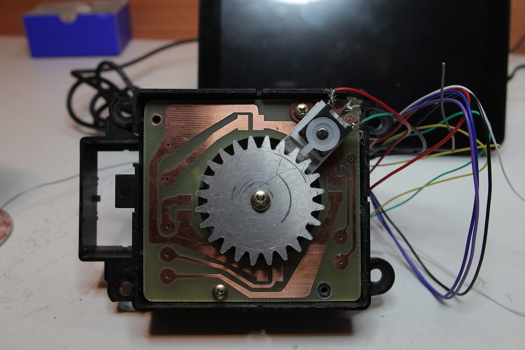
This based on a BMW iDrive controller,the toothed wheel I had laser cut especially for this.This has to do nothing more complicated than provide a simple on/off pulse when you turn the the controller in one direction,and the same but on another wire when you turn it in the other direction.The original mechanism has 24 detents that still work and match up with the number of teeth on the wheel that operates the microswitch.
It was designed to have surface mount microswitches on the PCB shown above,these didn't work so I have it like this instead..........

15780587590_7fd529f302_b.jpg


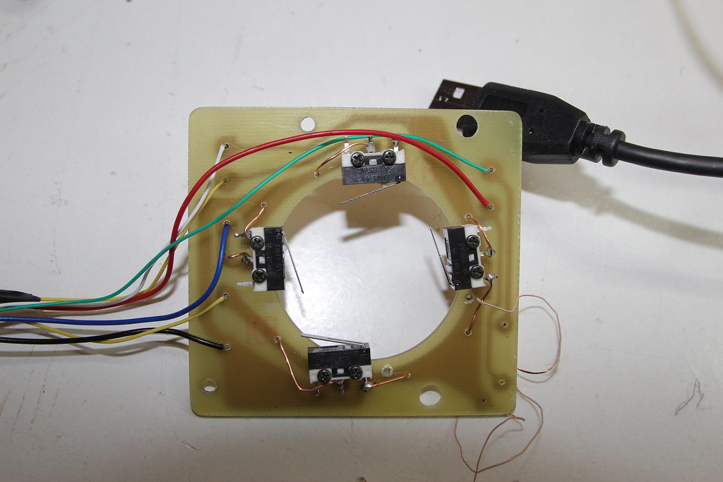
This gives me another four functions that are fed to a UHID keyboard emulator to control a media player,with the rotary motion being used for volume up and down.


I've already tried different sorts of optical encoders and it's a bit beyond what I'm capable of working with,so I really want to keep this as simple as possible and use good old fashioned mechanical switches but a lot more compact than what I've got at the moment.Is there at the very least an all-in-one switch that does this,the volume control function is essential and the whole point of this project,the other up/down/left/right functions I can do some other way if needed?I know there are some nice big vintage style rotary switches,but mostly they're too big,can't detect which way it's being turned and are too stiff to turn,this has to need very little effort to turn it.The exact number of detents isn't critical,but should ideally be between 20 and 30.

I have spent a long time on Google looking for such a switch,but when you don't know the name of it,it's difficult to know what to look for.
 
Last edited:
US Digital of Vancouver, WA make 8-pin DIP or SOIC ICs that do the rotary decoding (part numbers LS 7183 and 4). E
 
You could use a rotary quadrature encoder switch such as this one https://uk.farnell.com/alps/ec12e2424407/encoder-vertical-24-det-24ppr/dp/1520813
And use a circuit similar to Figure 4 on this web page to decode it into up and down pulses. https://www.digikey.com/en/articles...ary-shaft-encoders-assures-safety-and-control
You will also find them on ebay if you search for "quadrature encoder switch "rotary encoder switch"

Les
Ok thanks for the answers,but am I right in thinking these will only ever output gray code and will still need some sort of microcontroller to de-code it into the simple on/off pulse that I need? All I need is a ground pulse (actually 5 Volts would work as well) on one wire to increment the volume upwards,and a ground pulse on another wire to increment it down.I'd like to keep it as basic as possible so if it does go wrong,I can fix it myself.
I really need just a smaller and self contained version of what I've made above.

You can use a encoder board with a regular rotary quadrature device to generate the up/down pulses.
**broken link removed**
 
Figure 4 in the second link in my last reply gives a schematic. You can build this using the 74 series (74, 74LS, 74HC) or 4000 series logic ICs. You do not have to use a microcontroller or special function chip.

Les.
 
If you want to try the optical route, you can control the direction by having a stiff bit of wire wrapped 2 turns around the spindle, with a bit sticking out at each end, so it has a kind of slipping clutch action. Then you just have a slotted disk or whatever, your photo-interrupter, and the ends of your bit of stiff wire can press one of two switches so one tells you it's going up, the other one is for down. Sorry it's not a ready made thing, but it's light to turn if you do it right, can be quite compact, and you get the satisfaction of making it! (I saw this arrangement on a volume control on something once, so it's definitely been done before)
 
You can use a encoder board with a regular rotary quadrature device to generate the up/down pulses.
**broken link removed**
I've already tried it directly from an optical encoder and the pulses were too short at 1ms,these will be a lot less than that at 4us so won't work for me.
Figure 4 in the second link in my last reply gives a schematic. You can build this using the 74 series (74, 74LS, 74HC) or 4000 series logic ICs. You do not have to use a microcontroller or special function chip.

Les.
Again these will be VERY short pulses will they not,hence the desire for something that's purely mechanical?
If you want to try the optical route, you can control the direction by having a stiff bit of wire wrapped 2 turns around the spindle, with a bit sticking out at each end, so it has a kind of slipping clutch action. Then you just have a slotted disk or whatever, your photo-interrupter, and the ends of your bit of stiff wire can press one of two switches so one tells you it's going up, the other one is for down. Sorry it's not a ready made thing, but it's light to turn if you do it right, can be quite compact, and you get the satisfaction of making it! (I saw this arrangement on a volume control on something once, so it's definitely been done before)
As above^.
 
I've already tried it directly from an optical encoder and the pulses were too short at 1ms,these will be a lot less than that at 4us so won't work for me.

Again these will be VERY short pulses will they not,hence the desire for something that's purely mechanical?

As above^.

It would be simple to trigger a monostable that gates a slow pulse generator but that might be too complex for you.
 
Hi nsaspook,
I don't think think the op really wants a solution. The solution that throbscottle suggested would give pulses with a 50% duty cycle using just one channel from an optical encoder (Or switch type mechanical encoder). So an encoder that gave 20 pulses per rev would give a pulse duration of 1/40 of a rev. So if the minimum pulse length required was 1 mS then the maximum speed the encoder could be rotated would be 1000/40 = 25 revs per second which = 1500 revs per minute. I can't imagine that in the described application that it would be rotated at any were near that speed. The way he quotes the figures of 1 ms and 4uS are meaningless without also quoting the pulses per rev of the encoder and the speed of rotation.

Les.
 
The media player that this will be a volume control for has a range of 0-100 from muted to full volume. As 100 steps is a bit too sensitive,it increments upwards by 2 steps for every detent click and downwards by 6 steps for every click,this is set in the software of the keyboard emulator and can be changed if needed quite easily.

 
If all else fails I guess I could use my Arduino,butonly as a last resort as I'd still like to keep it as simple as possible.

Soooooooooooo.....................there has to be a ready made switch somewhere out there in the world that does what I need it to,but I have no idea what it's called?
 
You may want an Absolute encoder rather the quadrature incremental, there are many types out there and depending on the resolution you can get BCD decoding types also.
Max.
 
You may want an Absolute encoder rather the quadrature incremental, there are many types out there and depending on the resolution you can get BCD decoding types also.
Max.
Thanks for the suggestions,but again way more complicated than I really need.There must have been a purely electro-mechanical version of these before they invented quadrature and Gray code?
 
If all else fails I guess I could use my Arduino,butonly as a last resort as I'd still like to keep it as simple as possible.

Soooooooooooo.....................there has to be a ready made switch somewhere out there in the world that does what I need it to,but I have no idea what it's called?

This is why knowing how to actually program small low pin count controllers like a PIC12 is such a valuable skill for making one-off projects. You could then build/buy just about any type of indent system for tactile feedback with an optical encoder.

https://www.sparkfun.com/products/9117
 
Thanks for the suggestions,but again way more complicated than I really need.There must have been a purely electro-mechanical version of these before they invented quadrature and Gray code?

Sure, 30 or 40 years ago you could easily find them.
 
Quadrature encoders are the best bet for quality and feel , but expensive for 1 .

Economical, small, reliable, user feels detent.
Comes in **broken link removed**
EVQ-VVD00203B_sml.JPG

Look under Product Index > Sensors, Transducers > Encoders >


Optical encoders give higher resolution for 16 or 32 or more stops per rev. are what is used in modern stereo amps.

Then add decoder for Direction and Step pulse logic
article-2012august-motion-sensing-via-rotary-shaft-encoders-fig4.jpg
 
Hi Tony,
That looks like the information in the link I put in post #2 (And pointed out again in post #7) The OP claims the up and down pulses will be too short in duration. I think these pulses will have a 25% duty cycle. So with an encoder with 20 pulsed per rev even at 750 RPM I think the up/down pulses would be 1 mS in duration. I worked this out from this timing diagram below. (The edges of the up/down pulses in the above diagram do not seem to be in the correct position.
Quad01.jpg


This was drawn using a 3 input AND gate on the outputs instead of the strange gate symbol in the diagram (Which I assume is a 3 input NAND gate.)
 
Sure, 30 or 40 years ago you could easily find them.
So there should be plenty of them in the surplus shops,what ever they're called?

The above information is all very interesting,but is still more than I need:sorry:.What about something like this......

https://electronics-diy.com/rotary-encoder-for-ats-transceivers.php

A nice ready made solution that is designed to do almost exactly what I need it to? (Except that I can't find details anywhere how to buy the kit:confused:).
 
Status
Not open for further replies.

Latest threads

New Articles From Microcontroller Tips

Back
Top